What is Rudder Drop or Rudder wear down and how to measure it ?

What is Rudder Drop ?

Rudder Drop refers to the wear or downward shift of the rudder carrier’s bearing on a ship. As the bearing wears down, the rudder may lower, which can be measured to track the wear over time.

Rudder Drop

Must Read : Propeller Drop

How is Rudder Drop Measured?

Rudder drop is typically measured using a Trammel Gauge, which is an L-shaped instrument. The process involves:

  1. Marking Reference Points: A point is marked on the rudder stock, and another point is marked on the hull, usually within the steering gear room (on the Deck head girder).
  2. Initial Measurement: The distance between these two points is measured and recorded during the ship’s construction.
  3. Subsequent Measurements: Over time, the same distance is measured. The difference between the original measurement and the current measurement indicates the rudder drop or the extent of bearing wear.

Rudder Clearance and Jumping Clearance

Rudder clearance refers to the space between the rudder and hull. Pads are welded to both components, and this clearance allows for movement and wear. Over time, as the carrier wears down, this clearance, also known as jumping clearance, will increase.

Why is Jumping Clearance Necessary?

Jumping clearance is essential to prevent damage to the steering gear. The clearance ensures that excessive wear does not impact the functionality of the steering system. If this clearance increases significantly, it may indicate excessive wear on the rudder carrier bearing.

Steering Clearance

Steering clearance is the gap between the steering gear and the rudder assembly. Monitoring this clearance is crucial because as the carrier wears down, this gap will shrink, and any significant reduction could affect the overall steering performance of the ship.

In summary, rudder drop, jumping clearance, and steering clearance are all important factors to monitor to ensure the proper functioning and safety of the ship’s steering system.

How a Trammel Gauge Works:

A trammel gauge is a simple yet effective instrument used to measure the distance between two fixed points, typically on large structures like a ship’s rudder system. Here’s a breakdown of how it works:

  1. Structure of the Gauge:
    The trammel gauge is L-shaped, allowing for easy alignment with the two reference points. It has two adjustable pointers or arms that can be positioned to mark the distance between the points being measured.
  2. Reference Points:
  • One point is marked on the rudder stock (the vertical shaft connected to the rudder).
  • The other point is marked on the hull, typically in the steering gear room, on the Deck head girder.
  1. Initial Measurement:
    When the ship is constructed, the distance between these two points is measured and recorded using the trammel gauge. This serves as the baseline measurement for the rudder system.
  2. Subsequent Measurements:
    As the ship is used, wear and tear in the rudder bearing can cause the rudder to “drop” slightly. At regular intervals, the trammel gauge is used again to measure the distance between the same two points.
  3. Rudder Drop Calculation:
    The difference between the original distance (measured during construction) and the current distance (measured during inspection) is called the rudder drop or rudder wear down. This indicates how much the rudder bearing has worn down over time.

By comparing the two measurements, engineers can assess the wear on the rudder’s bearing and determine if maintenance or repairs are needed.

Turbocharger washing Procedure

Turbocharger Washing Procedure: You will Learn the Procedure of Cleaning Turbocharger in Details.

Turbocharger washing Procedure
Fig: Turbocharger washing procedure

Turbocharger is an important components of engine which increase the power to weight ratio of the engine. A turbocharger is an instrument fitted on the engine to increase the overall efficiency of the engine. Turbocharger affects the efficiency of the efficiency of engine. So, we need to washing it properly on time.

Suggested Read : Boiler Gauge Glass Blow through Procedure

What Is Turbocharger Washing

Turbocharger washing is the process of cleaning a Turbocharger for removing solid carbon deposits to keep it in good conditions. It is Important to wash turbocharger time to time between major repairs and ensure the engine runs smoothly. Regular cleaning is important because it helps remove deposits like carbon buildup, which can cause problems like poor engine performance and higher fuel consumption.

Why Washing Of Turbocharger Required ?

Let us first understand why turbocharger washing is necessary. If washing of blade of turbine and blower side is not done then a layer of air and exhaust gas formed on the blade. All Energy of exhaust gas not transfer to blade so, it does not rotate with adequate speed so, air required for combustion is not adequate so proper combustion does not takes place. Thus, we understand how fouling affects efficiency.

As due to fouling of blade there is decrease in efficiency of engine. so, need to do washing procedure of turbocharger on time. According to instructions mentions in the manual of turbocharger , washing is done.

What Important point before turbocharger washing

  • Keep in mind that , if you have not done the washing procedure of blade of blower and turbine from a long time then do not do washing procedure. Before doing washing procedure, make sure a complete overhaul of turbocharger is done. If you have not done overhauling ( if not cleaned for a long time ) and do washing of blade then deposits on the blade will not remove properly. some of the deposits left on blade. When Turbocharger run it create a Noise and heavy vibrations due to imbalancing of blade. It is very difficult to handle and cause break the some important part of the turbocharger.
  • For washing the blade of blower side, a separate connections is provided.
  • Fouling on the blade of exhaust side is less as compare to blower side. It is logical questions, everyone know. It is because due a high temperature and pressure gas falls on the blades and did the work of removing all the deposits accumulated on blade. As exhaust from combustion chamber contain some amount of impurity like caco3, carbon deposits and ash etc. So, some amount of exhaust deposits remain on turbine blade.
  • Sometimes, surveyor ask that , how will you know the efficiency of turbocharger is good. Again, this is tricky questions. Efficiency of Turbocharger can be get from Difference of inlet and outlet temperature of t/c. Because from difference, We can conclude that how much exhaust gas energy is is used or transferred to the blade for rotation.

Turbocharger Washing Procedure for Turbine side of Blade

Note :- When we will do water washing then we reduce the engine rpm. We also use Warm water instead of cold water At the pressure of 4.5 bar. WE do this because cold water and hot surface of blade cause cracking of blade of t/c due to quenching effect.

Procedure :-

  • First inform the bridge that we are going to t/c water washing.
  • Take the wind directions. Why we check wind directions ? it is because of fire hazards.
  • We have to decrease the RPM of engine before doing washing procedure. But speed will not decrease suddenly. Take at least 30 minutes to decrease the speed gradually. Keep decreasing speed till temperature of exhaust gas at the inlet of T/c is approximately 200-230 Degree Celsius.
  • When we reached at required rpm then wait and run the engine the engine at same speed for approximately 10-minutes so that temperature stabilizes.
  • Now open the drain of Turbocharger.

There Are two Valves provided, one for drain and other for supplying warm water.

  • As we already open the drain, now open the valve of water washing. Let it open for 10 minutes. Ninety percent of water get evaporated and ten % of water come from the drain.
  • Water coming out from the drain should be checked and if it is clean that means cleaning procedure is done properly. Now close the drain valve of T/c.
  • Now close the water supply valve. Run the engine at same speed for ten minutes. Then increase speed gradually. Meanwhile check abnormal vibrations or noise from t/c.

This is Water Washing Procedure of Turbocharger on turbine side.

Dry washing of Turbine side

There is a Box provided for putting a grit. Gauge glass fitted on it to check the level of grit.

There are three valve fitted to grit cylindrical box. One valve is for putting grit. another valve for supplying air. One valve is fitted at bottom of box which supply grit or air to turbine. name valve 4, 5 AND 6 in the above figure.

Valve 6 :- For supplying Grit to box.

Valve 5 :- For supplying air.

Valve 4 :- For supplying air of grit to inlet to turbine.

Dry washing is done at high RPM.

Increase the RPM of engine same as mention above to decrease And come speed at required RPM and let it run for 10 minutes and wait for all parameters to come stable. Check the air bottle pressure and drain it.

  1. First inform the bridge and check the directions of wind.
  2. Open the valve 6 and fill the grit in the box. Fill the grit up to 3/4 th level and close the valve.
  3. Open the Valve 4 grit will enter to turbine side.
  4. Open the Valve 5 and provide compressed and wait for a minutes and after that close it.
  5. From the sight glass and help of torch check all grit in turbine side is gone or not. But keep in mind that close the Valve 5 before seeing the conditions of grit,.

This is dry washing procedure of turbine side of turbocharger.

Dry washing of blower side of turbocharger

You to do the dry washing at high RPM. Follow the above procedure to increase the RPM and Run for ten minutes to stabilize all parameters.

Check the air bottle pressure and drain it.

Valve 3 :- For putting grit

Valve 2 :- Supplying air

Valve 1 :- For supplying air to blower side of turbocharger.

Open the Valve 3 and put the grit up to 3/4th level of box. Open the valve 1

Open the valve 2 and provide compressed air. Wait for a minutes and close valve 2 and the Valve 3.

This is all about washing procedure of turbocharger.

Advantages of water washing

The main advantages of water washing is that cleaning of blade is proper and increase the efficiency of T/C.

Disadvantages of water washing

  1. There is more chance on increase of corrosion of blade.. It is due to sulfuric acid in exhaust gas.
  2. If with water washing is not done properly cause noise or imbalance of blade and leads to break.
  3. It takes more time in cleaning.

So, because of the above reason we do grit washing. Note :- During grit washing make ensure that drain of t/c closed.

Difference Between Crosshead and Trunk Type Engine

Difference Between Crosshead and Trunk Type Engines

Crosshead and trunk type engines are two types of piston engines, each with distinct designs and applications. Here’s a detailed comparison:

Crosshead Engine

  • Design: It uses a piston rod and a crosshead assembly to separate the piston from the crankshaft. This design prevents lateral forces from acting on the piston, improving the durability of the engine.
  • Lubrication: Crosshead engines have separate lubrication systems for the cylinder and the crankcase, ensuring that high-pressure, high-temperature areas receive adequate lubrication.
  • Torque and Speed: These engines operate at low speeds and are ideal for large, low-speed applications like marine propulsion due to their high torque generation.
  • Size: Crosshead engines are taller and more complex because of their additional components, including the crosshead mechanism.
  • Maintenance: The separate lubrication system means less contamination in the crankcase oil, reducing maintenance costs and increasing engine life.

Trunk Type Engine

  • Design: The piston is directly connected to the crankshaft via a connecting rod without a crosshead assembly. This simplifies the engine but subjects the piston to side forces, which can lead to more wear.
  • Lubrication: A single lubrication system serves both the cylinder and the crankcase, which simplifies the design but can lead to more contamination.
  • Torque and Speed: Trunk engines are better suited for medium to high-speed operations, offering high power in compact designs, making them ideal for smaller vessels or auxiliary power units.
  • Size: These engines are more compact and shorter, requiring less vertical space.
  • Maintenance: The combined lubrication system increases the risk of contamination, resulting in higher wear and more frequent maintenance.

Difference Between Crosshead and Trunk Type Engines

Below is a detailed comparison between the two:

FeatureCrosshead EngineTrunk Type Engine
DesignUses a crosshead assembly to separate the piston from the crankshaft, reducing side thrust.The piston is directly connected to the crankshaft via a connecting rod, causing lateral forces on the cylinder.
LubricationSeparate systems for cylinder and crankcase lubrication.Single lubrication system for both the cylinder and crankcase.
Speed and PowerLow-speed, high-torque engines, ideal for large applications like marine propulsion.Medium to high-speed engines, suitable for smaller vessels and auxiliary units.
SizeLarger and taller due to the crosshead mechanism.More compact, requiring less vertical space.
MaintenanceEasier maintenance due to separate lubrication systems, leading to less contamination.Higher wear and contamination due to a combined lubrication system.
ApplicationsHeavy-duty applications such as large ships and low-speed operations.Used in smaller marine vessels, auxiliary engines, and high-speed machinery.
Cost and ComplexityMore expensive and complex to manufacture.Less expensive, simpler design.

Lubrication in 4 Four stroke engine

Introduction: Importance of Lubrication in 4-Stroke Engines

Lubrication in a 4-stroke engine is essential to maintain engine efficiency, minimize wear and tear, and ensure smooth operation. The internal components of an engine, such as the crankshaft, camshaft, pistons, and gears, move at high speeds and generate significant heat and friction. Lubrication plays a dual role: it reduces friction between these parts and also helps cool them by dissipating heat. This article will delve into the lubrication system used in 4-stroke engines, the key components involved, and the importance of proper maintenance.

How a 4-Stroke Engine Works

Before diving into the lubrication system, it’s essential to understand the working principle of a 4-stroke engine. The engine operates in four stages:

  1. Intake: The intake valve opens, allowing the air-fuel mixture to enter the combustion chamber.
  2. Compression: The piston compresses the mixture, preparing it for ignition.
  3. Power: The spark plug ignites the compressed mixture, causing a small explosion that pushes the piston downward, generating power.
  4. Exhaust: The exhaust valve opens, and the burnt gases are expelled.

Each of these strokes involves components that rely on proper lubrication to function smoothly. The following sections will explore the role of lubrication in each stage.

Wet Sump Lubrication System in 4-Stroke Engines

The wet sump system is one of the most common lubrication systems in 4-stroke engines. In this system, the engine oil is stored in a sump, typically located at the bottom of the engine. A pump circulates the oil from the sump through various parts of the engine, lubricating moving components and reducing friction.

Key components of the wet sump lubrication system include:

  • Oil Pump: Responsible for moving the oil from the sump to various parts of the engine.
  • Oil Filter: Filters out debris and contaminants, ensuring clean oil is circulated.
  • Oil Cooler: Helps in maintaining the oil’s temperature, preventing it from overheating.
  • Oil Galleries: Channels that direct oil to specific components such as the crankshaft, camshaft, and pistons.

Components Involved in Lubrication

  1. Crankshaft Bearings: The crankshaft plays a critical role in converting the piston’s linear motion into rotational motion. The crankshaft bearings are in constant contact with rotating parts, and without proper lubrication, these bearings would wear out quickly due to the intense heat and friction. Oil is pumped to these bearings, creating a film that prevents metal-to-metal contact.
  2. Piston and Cylinder Wall: The piston moves up and down within the cylinder, creating friction against the cylinder walls. Lubrication in this area is crucial, as it prevents excessive wear of both the piston and the cylinder wall. Oil splashes onto the cylinder walls, creating a thin film that helps to reduce this friction.
  3. Camshaft and Valves: The camshaft operates the opening and closing of the intake and exhaust valves, with these actions happening thousands of times per minute in a running engine. The camshaft and valve lifters require lubrication to minimize friction, prevent overheating, and ensure smooth operation. The oil flows through galleries that lead to the camshaft and rocker arms, allowing for effective lubrication of the valve train.
  4. Gear Systems: Many 4-stroke engines use gear systems to connect the crankshaft to the camshaft. These gears are subjected to heavy loads, and lubrication is necessary to reduce wear and tear. The oil film helps to ensure the longevity of these components, reducing the chances of gear failure.
  5. Turbocharger (if present): Some modern 4-stroke engines, especially those in marine or high-performance vehicles, are equipped with turbochargers. The turbocharger requires additional lubrication due to the extremely high speeds and temperatures at which it operates. Proper lubrication ensures that the turbo’s bearings do not fail prematurely, which could lead to a catastrophic engine failure.

Pressure Lubrication System

The pressure lubrication system, often integrated with the wet sump system, ensures that oil reaches critical components under high pressure. This system includes an oil pump, typically gear or rotor-type, which draws oil from the sump and forces it under pressure through the oil filter and into the oil galleries. From there, it is directed to key components like the crankshaft, camshaft, and piston rods.

In more complex engines, this system may also include an oil thermostat, which ensures that the oil is not too thick when cold or too thin when hot, providing the right consistency for optimal lubrication.

Lubrication of Auxiliary Components

In a 4-stroke engine, it’s not just the primary moving parts that need lubrication. Auxiliary components such as the timing chain or belt, fuel pump, and water pump also require lubrication to function effectively. These components are often lubricated by splashing oil or by being located in areas where the oil is circulated.

Oil Types and Their Properties

The choice of engine oil is vital for ensuring the engine’s longevity. Oils are categorized by their viscosity and performance standards. The viscosity of oil refers to its resistance to flow, and this property is essential because it determines how well the oil can form a protective film over moving parts. For instance, a low-viscosity oil might not offer enough protection in a high-temperature engine, while a high-viscosity oil may cause resistance and inefficiencies in a cold engine.

There are two main types of oils used in modern engines:

  1. Mineral Oils: These are derived from refined crude oil and are suitable for most everyday applications. They offer good protection but may need to be changed more frequently than synthetic oils.
  2. Synthetic Oils: Made from chemical compounds, synthetic oils provide superior lubrication, especially in extreme conditions. They have better thermal stability and can last longer between oil changes.

Cooling Effect of Lubrication

Apart from reducing friction, engine oil also plays a significant role in cooling the engine. As the oil circulates through the engine, it absorbs heat from components like the crankshaft, pistons, and bearings. This heat is then dissipated when the oil returns to the sump, where it cools before being recirculated.

Some engines are equipped with an oil cooler, which is similar to a radiator and helps to cool the oil further. This is particularly important in high-performance engines or engines that operate under heavy loads, where oil temperatures can rise significantly.

Common Lubrication Problems and Solutions

Despite the effectiveness of modern lubrication systems, problems can still arise. Some of the most common issues include:

  1. Oil Leaks: Gaskets and seals can wear out over time, leading to oil leaks. These should be addressed promptly, as oil leaks can lead to low oil levels and reduced lubrication.
  2. Oil Contamination: Dirt, debris, and metal particles can contaminate the oil, leading to engine damage. Regular oil changes and the use of high-quality oil filters can help mitigate this issue.
  3. Overheating: If the oil becomes too hot, it can lose its ability to lubricate effectively. This can happen if the engine is run under extreme conditions for prolonged periods without sufficient cooling.
  4. Sludge Build-Up: Sludge can form when the oil breaks down, usually due to infrequent oil changes or poor-quality oil. This can clog oil passages and reduce the effectiveness of the lubrication system.

Maintenance of Lubrication Systems

Proper maintenance of the engine’s lubrication system is critical for ensuring the longevity and efficiency of the engine. Some key maintenance practices include:

  • Regular Oil Changes: Follow the manufacturer’s recommended intervals for oil changes. This helps to ensure that the engine is always running with clean, effective oil.
  • Check Oil Levels: Regularly checking the oil level can help to identify leaks or excessive oil consumption before they cause major problems.
  • Inspect Oil Filters: Oil filters should be changed regularly to prevent contaminants from circulating in the engine.
  • Monitor Oil Pressure: Many engines are equipped with oil pressure gauges or warning lights. If the oil pressure drops too low, it could indicate a problem with the lubrication system that needs immediate attention.

Conclusion

Lubrication is a vital aspect of 4-stroke engine operation. From reducing friction to cooling critical components, the oil in a 4-stroke engine ensures that the engine runs smoothly and efficiently. Understanding the importance of each component in the lubrication system, as well as maintaining the system through regular oil changes and inspections, is essential for keeping the engine in optimal condition.

By paying attention to the lubrication system and using the correct type of oil, you can significantly extend the lifespan of your 4-stroke engine, reduce the likelihood of breakdowns, and improve overall performance. Proper lubrication is not just about preventing wear and tear—it is about optimizing every aspect of engine operation for maximum efficiency.

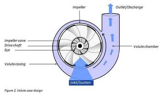
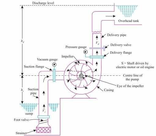
Why discharge valve closed during starting of centrifugal pump ?

In this Article, I have Explained Why discharge valve closed during starting of centrifugal pump ? Or Why centrifugal pump started with closed discharge valve ?

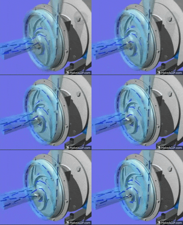
let us first understand through characteristics curve of centrifugal pump

A centrifugal pumps usually started with discharge valves shut.

Considering the properties of centrifugal pump by operating characteristic curve it is clearly found that; when the amount of water delivered is zero, the power available is at minimum.

So discharge valves valve remains shut off throughout the beginning to take care of low power demand by the pump on its motor having low power output at the beginning.


This helps stabilizing pumps at the starting. When the pump is stable the discharge valves opened and high power avaibility meets the high power demand; which might be not possible for the motor to fulfill for the starting 4-5 seconds.

Or

It is a very common practice to start large capacity centrifugal pump with the closed discharge valve .

If the characteristic curve for a centrifugal pump are examined it will be seen that when the quantity of water discharged is zero the power required by the pump is zero or very small amount.

by starting the pump with discharge valve closed the power demand made by the pump on the pump motor is kept to very minimum after the pump has started and the momentary high motor current demand has stabilized the discharge valve is opened.

Why centrifugal pump started with closed Discharge valve

By closing the discharge valve, the starting current can be reduced.

As we know, at the start of any motor, the current will be high. When we start the pump with an open discharge valve, the discharge head will act on the pump, i.e. more resistance, so that the motor has to give more starting torque to the pump, which means more current is drawn by the motor.

If we start the pump with discharge valve closed, it means there no discharge head and minimum resistance to the pump and so current drawn is minimum. Although the current taken during startup of motor is more than normal, but by closing the  discharge valve of centrifugal pump we can avoid extra load act on the pump.

If there is  a check valve, then the discharge valve can be opened. Without having a check valve, we need to have the discharge valve closed if there is pressure on the discharge side of centrifugal pump  at the time of startup.

If we think differently,If there is a pressure on the pump’s discharge side,before starting it may flow back through the pump,causing a backward spin and can draw more current , resulting damage to the pump.Thus can be prevented by keeping the discharge valve of centrifugal pump closed when starting.

Check Out Other Important Topics

Home

IC Engine

Electrical

Important PDFs

Boilers

Synergy Maritime Exam

Naval Arch

Interview Questions

Difference Between

Types of Pumps

Types of Valves

MEO Class 4

Auxiliary Machines

Electric Traction

What is Electric Traction

Electric traction refers to the use of electricity to power vehicles, typically trains and trams, but it can also apply to electric buses and some types of electric cars. This method of propulsion replaces traditional methods like steam engines or diesel engines with electric motors. Electric traction offers several advantages, including greater efficiency, reduced pollution, and the ability to provide smooth and quiet operation.

components of electric traction

Electric traction systems consist of several key components that work together to convert electrical energy into mechanical power for propulsion. The specific components may vary depending on the type of electric traction system and the vehicle, but here are the essential elements commonly found in these systems:

  1. Power Source: This is the origin of the electrical energy used for propulsion. It can include overhead wires (catenary system), a third rail, or onboard batteries.
  2. Substation: In the case of overhead wires or a third rail, substations are used to convert and distribute high-voltage electricity to the traction system at a suitable voltage for the vehicle.
  3. Electric Motor: The electric motor is the central component responsible for converting electrical energy into mechanical motion. There are two main types of electric motors used in traction systems:
  • Direct Current (DC) Motor: Commonly used in older electric traction systems.
  • Alternating Current (AC) Motor: More commonly used in modern electric traction systems due to its higher efficiency and adaptability.
  1. Power Electronics: Power electronics components, such as inverters and converters, control the flow of electricity to the electric motor. They help manage power output, speed control, and energy regeneration during braking.
  2. Transmission System: Some electric traction systems include a transmission to transfer power from the motor to the vehicle’s wheels, especially in larger vehicles like trains and buses. In contrast, many electric cars use a single-speed transmission.
  3. Drive Wheels: These are the wheels that receive power from the electric motor and provide the necessary traction to move the vehicle.
  4. Control Systems: Advanced control systems manage various aspects of the electric traction system, including speed control, acceleration, braking, and energy management. These systems ensure safe and efficient operation.
  5. Regenerative Braking System: Many electric traction systems incorporate regenerative braking, which allows the electric motor to act as a generator during braking. This process recovers some of the energy and stores it or returns it to the power source, improving energy efficiency.
  6. Energy Storage (Batteries): In battery-powered electric vehicles, energy storage systems, typically lithium-ion batteries, store electrical energy for later use. These batteries provide power to the electric motor and store energy during regenerative braking.
  7. Charging Infrastructure (for battery-powered vehicles): Electric vehicles require charging infrastructure to replenish their batteries. This can include charging stations at homes, workplaces, and public locations.
  8. Current Collectors (Pantographs or Collecting Shoes): In overhead wire systems, vehicles use current collectors, such as pantographs or collecting shoes, to establish contact with the overhead wires and draw electricity.
  9. Safety Systems: Electric traction systems include safety features to ensure the protection of passengers, operators, and the public. These may include circuit protection, emergency braking systems, and safety interlocks.
  10. Auxiliary Systems: Electric traction vehicles have auxiliary systems like lighting, heating, and air conditioning, which are powered by the electric system or an auxiliary battery.

These components work together to provide efficient, clean, and reliable propulsion in various modes of transportation, from electric trains and trams to electric buses and cars. The specific configuration and components can vary based on the application and technology used.

Electric Traction Working

Electric traction is a method of powering vehicles, most commonly seen in trains, trams, electric buses, and electric cars. At its core, electric traction harnesses electrical energy to generate mechanical motion, propelling the vehicle forward. The process commences with an energy source, typically overhead wires, a third rail, or onboard batteries, providing the necessary electrical power. In the case of overhead wires or a third rail, substations help regulate and distribute electricity to the traction system.

The heart of the system is the electric motor, which plays a pivotal role. Electric motors can be of two main types: direct current (DC) or alternating current (AC) motors. These motors convert the electrical energy into rotational motion through electromagnetic principles, generating the force required for movement. This rotational motion is then transferred to the vehicle’s drive wheels, enabling the vehicle to move.

Sophisticated control systems are vital for governing the electric traction system. These systems regulate speed, acceleration, and deceleration, ensuring safe and efficient operation. Many electric traction systems also feature regenerative braking, which turns the electric motor into a generator during braking, recovering and storing energy for later use, thus enhancing energy efficiency.

Additional components, such as energy storage systems, safety mechanisms, and auxiliary systems for passenger comfort, contribute to the overall functionality of electric traction. This environmentally friendly and versatile mode of transportation continues to advance through ongoing technological developments, making it an essential part of modern, sustainable mobility solutions.

Application of Electric Traction

Electric traction has a wide range of applications in the field of transportation and is used in various modes of transit. Here are some of the key applications of electric traction:

  1. Electric Trains: Electric traction is extensively used in railway systems worldwide. Electric trains are known for their efficiency, speed, and low environmental impact. They are commonly used for both passenger and freight transportation, providing a reliable and sustainable mode of transit.
  2. Trams and Light Rail: Trams and light rail systems in urban areas often rely on electric traction. These systems are known for their ability to efficiently move large numbers of passengers within cities, reducing traffic congestion and air pollution.
  3. Subways and Metro Systems: Many subway and metro systems are powered by electric traction. These underground and elevated rail networks offer fast and efficient mass transit options in densely populated urban areas.
  4. Electric Buses: Electric buses have gained popularity as a cleaner alternative to traditional diesel or natural gas buses. Electric traction technology is used to power the motors in these buses, reducing emissions and noise pollution in urban environments.
  5. Electric Cars: Electric traction is also applied in electric cars, which are becoming increasingly popular due to their environmental benefits and advancements in battery technology. Electric cars use electric motors for propulsion, offering a more sustainable and energy-efficient mode of personal transportation.
  6. Electric Trucks: Some commercial trucks and delivery vehicles are now using electric traction systems. Electric trucks help reduce emissions and operational costs, making them suitable for urban deliveries and short-haul transportation.
  7. Mining and Industrial Equipment: Electric traction is used in mining trucks, excavators, and other industrial equipment. Electric-powered machinery offers greater torque and efficiency compared to traditional diesel engines, making it suitable for heavy-duty applications.
  8. Cable Cars and Funiculars: In hilly or mountainous areas, cable cars and funiculars often use electric traction to transport people and cargo. These systems rely on electric motors to move cable cars up steep inclines.
  9. Material Handling Equipment: Electric traction is common in warehouses and manufacturing facilities for material handling tasks. Electric forklifts, pallet jacks, and other equipment benefit from the efficiency and clean operation of electric motors.
  10. High-Speed Rail: Electric traction is essential for high-speed rail systems, which are used in some countries for fast and efficient long-distance passenger transportation.
  11. Marine Transport: Electric traction is also used in some electric ships and boats, particularly in applications where reduced emissions and quiet operation are important, such as passenger ferries and some smaller vessels.

Electric traction is a versatile technology that continues to advance, contributing to cleaner and more efficient transportation options across various industries. Its applications play a crucial role in reducing greenhouse gas emissions and promoting sustainability in transportation systems.

Advantages of Electric Traction

Electric traction offers numerous advantages, making it a compelling choice for various modes of transportation:

  1. Environmentally Friendly: Electric traction systems produce no tailpipe emissions, contributing to cleaner air and reduced pollution in urban areas.
  2. Energy Efficiency: Electric motors are highly efficient, converting a significant portion of electrical energy into mechanical power, resulting in energy savings.
  3. Cost Savings: Operating electric traction systems is often cheaper due to lower electricity costs and reduced maintenance requirements.
  4. Enhanced Performance: Electric motors provide instant torque, leading to quicker acceleration and smoother power delivery, improving overall vehicle performance.
  5. Reduced Noise: Electric vehicles are quieter than their internal combustion counterparts, reducing noise pollution and creating a quieter urban environment.
  6. Versatility: Electric traction technology can be adapted for various applications, from electric cars to trains, making it versatile and scalable.
  7. Reduced Fossil Fuel Dependency: By utilizing electricity, electric traction systems can incorporate renewable energy sources, reducing reliance on fossil fuels and promoting sustainability.
  8. Regenerative Braking: Many electric traction systems use regenerative braking, recovering and storing energy during braking, which enhances overall energy efficiency.
  9. Long-Term Sustainability: Electric traction systems are often designed for longevity, reducing waste and contributing to sustainability.
  10. Government Incentives: Governments often provide incentives and subsidies to encourage the adoption of electric traction vehicles, making them more attractive to consumers and businesses.
  11. Continuous Technological Advancements: Ongoing research and development in electric traction technology lead to continuous improvements in battery technology, charging infrastructure, and overall system efficiency.
  12. Lower Carbon Footprint: When powered by renewable energy sources, electric traction systems significantly reduce their carbon footprint, contributing to efforts to combat climate change.

These advantages collectively demonstrate the compelling case for the adoption of electric traction in modern transportation systems, offering not only environmental benefits but also economic and performance advantages.

Disadvantages of Electric Traction

Electric traction, while offering numerous advantages, also comes with some disadvantages:

  1. Limited Range: Electric vehicles (EVs) typically have a limited driving range compared to vehicles with internal combustion engines. This limitation can be a concern for long-distance travel without frequent charging infrastructure.
  2. Charging Infrastructure: The availability and convenience of charging infrastructure for electric vehicles can vary widely by region, which can be a barrier to widespread adoption.
  3. Charging Time: Charging an electric vehicle takes longer compared to refueling a traditional vehicle with gasoline or diesel. Fast-charging stations exist but may not be as widespread.
  4. Upfront Cost: Electric vehicles often have a higher upfront purchase price than their gasoline counterparts, although this cost difference is gradually decreasing as technology improves.
  5. Limited Model Options: The variety of electric vehicle models available may be limited compared to traditional vehicles, although this is changing as more automakers introduce EVs.
  6. Battery Degradation: Lithium-ion batteries, commonly used in electric vehicles, can degrade over time, leading to reduced driving range and the eventual need for expensive battery replacement.
  7. Charging Time vs. Range Anxiety: Concerns about running out of charge (range anxiety) and the time needed to recharge can be a psychological barrier for some potential electric vehicle buyers.
  8. Energy Source Impact: The environmental benefits of electric traction systems depend on the energy source used for electricity generation. If electricity is primarily generated from fossil fuels, the carbon footprint may not be significantly reduced.
  9. Weight: Electric vehicles tend to be heavier due to the weight of the battery pack, which can affect handling and overall vehicle efficiency.
  10. Infrastructure Investment: Developing a comprehensive charging infrastructure requires significant investment, which may pose challenges for governments and organizations.
  11. Electricity Grid Demand: Widespread adoption of electric vehicles could place increased demand on the electricity grid, requiring upgrades to handle the load.
  12. Disposal of Batteries: Proper disposal and recycling of lithium-ion batteries are essential to prevent environmental issues, and the process can be complex and costly.
  13. Noise Concerns for Pedestrians: Electric vehicles are quieter than traditional vehicles at low speeds, potentially posing safety concerns for pedestrians who rely on auditory cues.
  14. Cold Weather Performance: Extreme cold can negatively impact the range and performance of electric vehicles, as it affects battery efficiency.
  15. Limited Fueling Options for Some Applications: In specific industries like aviation and long-haul shipping, electric traction may not yet be a feasible option due to limited battery technology.

It’s important to note that many of these disadvantages are being addressed through ongoing technological advancements, increased investment in charging infrastructure, and supportive government policies. As electric traction technology continues to evolve, some of these disadvantages may become less significant over time.

Fresh Water Generator On Ship

In this article, I am going to discuss about an equipment called Fresh water Generator which is used onboard to produce fresh water on ships. We will discuss it’s working principle, types, how it operates and it’s troubleshooting.

If you any doubt or any problems related this Topic. You are at right place. After reading this Article on this topic, I am damn sure you will not have any Doubts remaining.

In this Article, you will learn :-


What is Fresh Water Generator ?

A Fresh water generator is a Device which is used on ship for production of fresh water from ocean water for domestic and auxiliary functions , which is a vital demand aboard ships.

A considerable quantity of H2O is consumed in a ship.

The crew consumes an average 100 liter/head/day. In a steam ship (a ship whose main propulsion unit is a turbine or a ship which could be a giant tanker with turbine-driven oil pumps) the boiler consumption may be as high as thirty tons per day.

The equipment used on board to generate freshwater from seawater is known as a freshwater generator.

It is used to produce fresh water onboard for drinking,cooking, washing etc.

How pure Water produced on ship ?

Pure water produced on ship ships generally using two principles or Method ; either

  1. Distillation or
  2. Reverse Osmosis.

Reverse osmosis is normally used in passenger ships where large quantities of water is consumed .

Here I am trying to illustrate the working principle of the freshwater generator that works on the basis of the distillation principle that is very common in cargo ships.

Distillation Systems

Fresh water from sea on ship is produced mainly by Distillation process.

What is Distillation ?

  • Distillation is the method of production of pure water from sea water by evaporating and re condensing .

Distilled water is made as a results of evaporating ocean water either by a boiling or a flash process.

This evaporation enables the reduction of the 3200 parts per million of dissolved solids in sea water down-to the one or two percent in distilled water.


Boiling process

This type of evaporator boils sea water at a saturation temperature corresponding to the evaporator pressure and is known as a boiling evaporator.

In a boiling Evaporator, water is maintained continuously at its saturation temperature-in other words, Latent heat is added.

While in the flash evaporator, sensible heat is supplied.

  • Submerged tube type- Boiling Evaporator or tube type
  • Boiling Process Evaporator ( low pressure evaporator ) Alfa laval or plate type :-

This both type of generator discuss below in details.

Suggested Read: Oily Water Separator


Flash Process (Flash Evaporator )

  • This type of evaporator heats the water in one compartment before it is released into a second compartment in which the pressure is substantially lower, causing some of the water to flash into vapour .
  • This type of evaporator is known as flash evaporator .
  • In flash evaporator, sensible heat is supplied.

Types /classification

On the basis of of Working Principle ,it is classified into

  1. Distillate Type
  2. Reverse Osmosis
  • Distillation is cheaper and efficient for less quantity, but RO is expensive and used for production in a large quantity.
  • RO is used on a passenger ship, where a large amount of water is consumed.

  1. Distillation = (Evaporation + Condensation)
  2. Reverse Osmosis = (Semi permeable membrane – filter)

Distillate type is again classified based on the evaporator and condenser structure, i.e

  1. Plate type and
  2. Tube type fresh water generator
  • Tube type ,also known as the submerged type, because the steam coils are submerged.
  • Sometimes it is known as Boiling FWG.


Main or Various type of fresh water generator which are mainly used on ships are :

  1. Submerged Tube Type
  2. Plate Type
  3. Reverse Osmosis Plant

Suggested Read: Steering gear


The main body of a fresh water generator on the ship consists of

  1. Heat Exchanger,
  2. Distillate pump
  3. ejector pump,
  4. air brine eductor
  5. Salinometer
  6. demisters or mesh separator,

1.Heat exchanger

  • Evaporator :- It is used to boil off the sea water at lower temperature with the help of vacuum created inside the fresh water generator shell.
  • Condenser: It use s the sea water to cool down; and condense the steam to achieve distilled water

2.Fresh Water Pump / Distillate pump

  • It is used to supply the generated fresh water to ship’s fresh water tank by taking the suction from fresh water generator.

Normal rated capacity -3m^3/hr

3.Ejector pump

  • It is used to supply pressurised water to the eductor for creating vacuum.It also supplies cooling water to condenser(to cool the fresh water vapours)

Rated capacity–20-30m^3/hr

Pressure- 3-6 bar

4.Air brine eductor:

  • It is used to to remove accumulated brine and salts deposits from the generator and create necessary vacuum.

5.Salinometer:

  • It is connected to the distillate output just before the solenoid operated three way valve. It is used for measuring the ppm of fresh water produced which is generally (1-2ppm)

The salinometer works on the simple principle that pure water does not conduct electricity; and its conductivity increases with increased dissolved impurities and salts.

Suggested Read: Purifier


What is demisters in Fresh Water generator ?

6. Demisters:

  • This is used to separate sea water droplet from the steam vapour.
  • A demisters is a thickened layer of mesh structure; fitted in between the evaporator and the condenser element.
  • A demisters can be made of nickel, monel metals, copper, stainless steel and synthetic fibers; such as Polypropylene and PVC.
  • Typically; demisters made of monel metal are used for the generation of fresh water.
  • when the water evaporates it carry over some fine little molecules of water along with the rising steam.
  • When the source of such water is sea; it can considerably increase the salinity of output water.

So to maintain salinity as low as 5 to 15 ppm; we use demisters which restrict the passage of mist and pass dry steam.

How Fresh Water Generator Works ?

Working Principle

  • The basic principle of all low-pressure freshwater generators is that the boiling point of the water can be reduced by reducing the pressure of the surrounding atmosphere.
  • Water can be boiled at low temperatures by maintaining a low pressure, say 50 degrees Celsius.The heat source for the freshwater generator could be waste heat rejected by main engine jacket cooling water.
  • Hence,boiling can take place at about 40 to 60 degrees Celsius by using energy from a heating coil and by reducing pressure in the evaporator shell.
  • This type of single-effect plant is designed to provide a better economy than obsolete boiling evaporators.

Suggested Read: What are the uses of Filter ?


Plate Type Fresh water generator ( Alfa – level Type ) Working

  • If the condenser and evaporator Heat exchangers of a fresh water generator is composed of plates then that type of freshwater generator is called Plate type freshwater generator.
  • The main components are condenser and evaporator heat exchangers, brine air ejectors, seawater pumps, distillate pumps, salinometer, demister, water flow meters, etc.

Below You can see the line diagram.

Fig :- Plate Type ( Alfa – Lavel Type )

  • Fresh water generator uses heat from main engine jacket cooling system which often cooling the engine passes through evaporator to evaporate the sea water feed into it.
  • But the jacket cooling water temperatures available is about 70-80 degree celcius,whereas boiling of water is 100 degree Celsius at 1 atm.
  • so in order to evaporate sea water at 70 degree Celsius we need to reduce pressure.
  • This is done by creating vacuum inside chamber si that sea water get evaporated below 100 degree celcius and also vacuum helps to evaporate easily.
  • This vaccum is created by air or brine ejector.
  • Now,the evaporated sea water passes through demisters which scrubs off sea water droplets from water vapour.
  • Unevaporated water/ particles is discharged as brine (by means of a combined air / brine ejector).
  • This vapour passes through the condenser which condense the vapour and get collected at the bottom which is transferred to fresh water tank ,where it is passed through salinometer and controlled by three way solenoid valve.
  • The feed rate to the evaporator is fixed at the feed inlet to the evaporator by the orifice plate throughout the entire process.
  • If the salt content of the produced water is high, the solenoid valve diverts the freshwater to the shell side of the freshwater generator and emits an alarm signal.
The solenoid controlled dump valve diverts the flow back to the shell in case of fresh water salinity exceeding a predetermined value (maximum usually 10 ppm).
This prevent contamination of the made water.Excess salinity caused by so many factors including leakage of seawater at condenser or priming of evaporator or malfunctioning of demister, or many other reasons.In FWG,What cannot be condensed at the condenser Is called ‘incondensable gasses’ such as air and these gases are continuously ejected out by air/brineejector.This way, the fresh water generator shell is kept at high vacuum, which is a must to boil water at low temperatures.Suggested Read:

Tube Type Fresh Water Generator

  • Tube type FWG also, known as the submerged type, because the steam coils are submerged.
  • Sometimes it is known as Boiling FWG.
  • The working and principle of the freshwater type tube generator is the same as the plate type fwg.
  • Only difference in instead of plates, condenser and evaporators are tubes.

A typical freshwater generator tube-type line diagram is given below..

  • The submerged tube type fresh water generator uses heat from the main engine jacket cooling water to produce water drinkable,by evaporating seawater due to high vacuum, which allows the feed water to evaporate at a comparatively low temperature.Steam can also be used as a source of heat instead of the main engine jacket cooling water.
  • This type of freshwater generator is based on two sets of shell and tube heat exchangers, one act as an evaporator or heater and the another act as a condenser.
  • The combined air / brine ejector creates vacuum condition in the evaporator chamber by driving sea water through the air / brine ejector and sea water supplied by the ejector pump to be delivered to the ejector for taking out the brine (concentrated seawater) and air.
  • The temperature of the feed water in the evaporator chamber is about 50 degrees Celsius. The rate of supply of water to the evaporator is fixed by an orifice fitted at the feed inlet.
  • Due to the vacuum condition inside the evaporator, the feed water evaporates at this temperature.The water spray and the droplets are partly removed from the vapor by the deflector mounted on the top of the evaporator and partly by the demister.
  • The water droplets, which are separated, fall back into the brine, which is extracted by the water ejector.
  • The desalted vapor, which passes through the demister, will come into contact with the condenser, where it will be condensed by incoming cold sea water.
  • The distilled water is then removed by an integral freshwater pump (distillate pump) and controlled by a salinometer and a solenoid valve.
  • If the salt content of the water generated is high, the solenoid valve transfers the freshwater to the freshwater generator shell side and gives an alarm signal.
  • To get a better suction head, the distillate pump is placed in the freshwater generator plant at the lowest possible location.This is because the shell of the freshwater generator is at a lower pressure.

With the height of liquid column in the suction line, the distillate pump gets maximum net positive suction head.

Thermometers are installed to control the seawater to the condenser and the cooling cooling water to the evaporator .These thermometers did the work of controlling of both heating and cooling of these units.

The salinometer or salinity indicator is connected to the remote alarm, so that at the ship’s engine control room, very high salinity is immediately registered.

What are Safety device fitted on Fresh Water generator ?

  • relief valve
  • vaccum gauge
  • vent cock
  • thermometer

What are faults in fresh water generator

What happens when there is fault in FWG ?

  • Faults in the freshwater generator reduce the performance of the system, reducing the quality and quantity of freshwater produced on ships.
  • These irregularities must be identified and corrected immediately to ensure that the optimum performance of the freshwater generator is achieved.

Faults in FWG are :-

1.Loss of Vacuum or Over-pressure of Shell

What reasons may there be for vaccum losses in a fresh water generator?


The shell pressure of the freshwater generator increases and the rate of freshwater produced decreases.

The reasons are:

a) Air leaks into the evaporator shell in large quantities and air ejector cannot cope.

b) The cooling water flow through the condenser is reduced or cooling water temperature is high.

This cause saturation temperature and hence saturation pressure within the condenser to rise.

c) Malfunctioning of the air ejector.

d) Flow rate of the heating medium increased and excess water vapour produced.

Since this excess vapour can not be condensed, the pressure of the shell increases or the vacuum drops.

2.Salt Water Carry Over

During the operation of the freshwater generator salt water can be carried over in large quantities.

This is called priming.

General reasons of the priming are:

a) Level of salt water inside the shell is high.

When water level is high agitation due to boiling occurs and salt water may carry over along with the vapours.

b) When there is a high level of water agitation due to boiling and salt water may be carried along with the vapours.

c) Rate of evaporation increased.

3.Gradual Increase in Level of Brine

A constant level of brine must be maintained in the shell for the satisfactory operation of the freshwater generator.

Brine is the concentrated water of the sea after the release of water vapours.

This brine is gradually extracted from the shell. Typically, this is obtained by the combined air-brine ejector.

It extracts air as well as brine from the shell of fwg.

Any fault with the ejector or the brine extraction pump (in some models) causes the brine level to increase.

4.Increase in Salinity of Freshwater

Possible causes are:

a) Brine level inside shell too high.

b) Leaking condenser tubes or plates.

c) Operation of evaporator near shore with contaminated feed water.

d) Shell temperature and pressure too low.

e) Increased solubility of CO2 generated from the salt water due to reduced sea water temperature.

This dissolved CO2 makes water acidic and conductivity of water increases.

Salinometer therefore shows increased salinity, which is a measure of conductivity and non-salt presence.

How Scale Formation Occurs in Fresh Water Generator

Fresh water generator performance reduces with scale formation because it causes reduction in heat transfer efficiency.

In FWG three scales are normally found these are :-

Calcium Carbonate, CaCO3
Magnesium Hydroxide, Mg(OH)2
Calcium Sulphate, CaSO4

The formation of calcium carbonate and magnesium hydroxide depends mainly on the operating temperature.And,the formation of calcium sulphate depends mainly on the density of the contents of the evaporator or the brine.The reaction takes place when the sea water is heated:

Ca(HCO3)2 ————> Ca + 2HCO3

2HCO3 ————> CO3 + H2O + CO2

If it is heated up to approx. 80 degrees Celsius

CO3 + Ca ————> CaCO3

If it is heated above 80 degrees Celsius

CO3 + H2O ————> HCO3 + OH

Mg + 2OH ————> Mg(OH)2

Hence, if the sea water is heated to a temperature below 80 degrees Celsius in the freshwater generator, the calcium carbonate scale will predominate.
The magnesium hydroxide scale is deposited when sea water is heated above 80 degrees Celsius.

If the evaporator content density is greater than 96000 ppm, the calcium sulphate scales are formed.But, brine density of FWG is normally 80000 ppm and less.Hence, the formation of scales due to calcium sulphate is not a problem.

That’s why It is recommended that the freshwater generator be operated at its rated capacity, not more.More water production than the rated capacity means a higher concentration of brine and a more formation of scale.Similarly higher shell temperatures result in hard scale formation that will be hard to remove.All of these together will dramatically reduce efficiency of plant.

How to minimize scale formation

The formation of a scale in a freshwater generator can be controlled and minimized by continuous treatment of chemical.

Marine engineers prefer polysulphate compounds (such as sodium polysulphate) with anti-foam, which are commonly used on ships.

These chemicals reduce the scale formation of calcium carbonate and possibility of foaming.

The compound is

  • non toxic,
  • no-acidic,

and can be used in fresh water generator producing water for drinking purposes.

It will be continuously feed via a metering pump or by gravity to the feed line.

The quantity of chemical to be dosed depends on the capacity of the fresh water produced.

The main thing is that,this chemical doses is effective only on low pressure fresh water generators.

The temperature of the sea-water is less than 90 degrees.

In order to maintain performance of Fresh water generator chemical treatment to be religiously carried out.

What are the causes for low production of Fresh Water ?

Reasons of Low Production are following :-

  1. Ships draft is less.
  2. level of brine is too high.
  3. Filter before ejector pump is dirty .
  4. Faulty ejector pump- not developing enough pressure
  5. Faulty Ejector nozzle/ nozzle chocked
  6. Incorrect feed
  7. scale formation in evaporator
  8. shell temperature is too high
  9. scale formation in condenser
  10. condenser cooling water flow is reduced
  11. Condenser cooling water temp. too high
  12. Incorrect assembly of plates
  13. Leakage in plant like from pressure gauge, vent, distillate pump seal etc.
  14. Distillate pump faulty
  15. Faulty flow meter
  16. Faulty solenoid valve

How Do I Start a fresh water generator ?

Starting of fresh water generator

Starting the Fresh Water Generator,few important point to be noted:-

We need to check before starting the fresh water generator that the ship is not in congested water, canals and is 20 nautical miles away from the shore.This is done because the effluents from factories and sewage are discharged into the sea near the shore which can get into the FWG.

Check whether the engine runs above 50 rpm, which is because the temperature of the jacket water at low rpm is around 60 degrees and is not sufficient for water evaporation.

  1. Check the drain valve is in close position,Which is present at the bottom of the generator.
  2. Now open the sea water pump’s suction and discharge valves which provide water for evaporation, cooling, and to the eductor for vacuum formation.
  3. Open the seawater discharge valve through which the water is sent back to the sea after , circulating inside the freshwater generator.
  4. Close the vacuum valve, which is situated on top of the generator.
  5. Now, we should Start the sea-water pump and check the pump pressure. In general, the pressure is 3-4 bar.
  6. Wait until the vacuum builds up. Vacuum should be at least 90 percent, which can be clearly seen on the generator gauge ,situated on FWG . The time taken for vacuum generation is usually around 10 minutes.
  7. When vacuum is achieved, open the valve for the treatment of feed water, this is designed to prevent the formation of a scale within the plates.
  8. Now open the inlet and outlet valves of hot water (jacket water), slowly to about half.Always,First open the outlet valve and then the inlet valve. Slowly start increasing the opening of the valves to full opening.
  9. Now we can see that the boiling temperature starts to rise and the vacuum starts to fall.
  10. The vacuum drops to about 85 percent, which is an indication that evaporation begins.
  11. Open the valve for drain from the fresh water pump.
  12. Switch ON to the salinometer if it has to be started manually. Generally, it’s on the auto start mode.
  13. Now start the fresh water pump and test the water that comes out of the drain.
  14. When fresh water starts generating, it can be seen that the boiling temperature drops slightly again and that the vacuum goes back to normal value.
  15. Check that the water, which coming out of the salinometer is not salty and also check the reading of the salinometer.This is done to see whether the salinometer is working properly or not, and to avoid contamination of the entire fresh water with salt water.Salinometer values are kept below 10ppm.
  16. Open valve for tank from the pump and close drain valve after testing the taste of the water coming out of the salinometer.


Fresh water Generator Stopping Procedure

It is desirable to stop the fresh-water generator as ship approaches port, shallow water, etc.This is because the seawater may contain harmful bacteria that can enter into the produced freshwater.The operation of freshwater should be carried out in consultation with the bridge watchkeeper.

Following, procedure to stop the fresh water generator can be adopted.

  1. Open the bypass valve , slowly for main engine jacket cooling water.
  2. Ensure that the cooling water temperature of the main engine jacket is within normal limits.
  3. Close inlet and outlet valves of jacket cooling water for the freshwater generator respectively.
  4. Close the feed water chemical dosing valve.
  5. Stop the distillate pump and shut down the discharge valve.
  6. Switch off the salino meter.
  7. Close the filling valve of the freshwater tanks.
  8. Wait for the temperature of the evaporator shell to drop below 50 deg celcius.
  9. Close the evaporator feed-water valve.
  10. Stop the pump ejector. Shut down overboard valve of fresh water generator.
  11. Open the vacuum breaker valve so that the side pressure of the shell is equal to the atmospheric pressure.
  12. Open the evaporator drain valve to drain all the seawater from the freshwater generator.

Precautions for Operation of Fresh water Generator

  1. The pressure of seawater at the inlet of air ejector must be 3 bar or more.
  2. The ejector outlet pressure should not exceed 0.8 bar.
  3. The distillate pump of fresh water generator never start in dry condition.
  4. To prevent thermal shock to the main engine, operate the jacket cooling water valves slowly to the fresh water generator.
  5. Feed water to be supplied to cool down the evaporator for a few minute before stopping.
  6. Never open the evaporator drain valve before the vacuum breaker is opened. Otherwise, the atmospheric pressure causes seawater to hit the deflector insiders.

In this Article,I have written answers to all Questions arises on this Topic which I have learned from my faculty or from books.

Anything I missed ? Please write it down in the comment section and don’t forget to share it, because sharing is caring.

Wikipedia

Follow me on Twitter :- Click Here

Check Out Other Important Topics

Read More: What is the Function of Air Compressor ?

Read Here : Frequently Asked Questions in Interview

Frequently Asked Questions ( FAQ )

What are the two types of fresh water generator?

Two Types are :-
1. Submerged tube type
2. Plate type

Method of generating Fresh water on Ship

1. Fresh Water Generator…
2. Reverse Osmosis

What is the importance of fresh water generator?

It is An important part on Ship because it is used for generating fresh water. Fresh water generated is used for drinking, cooking, washing, and even powering important machinery that uses fresh water as a cooling medium.

What are the two simple working principle of fresh water generator?

1. distillation and
2. effect of pressure on boiling point.

What is condenser in fresh water generator?

The clean vapour is condensed after it has been filtered by being cooled again in the condenser.

What happens when vacuum reaches 100% in fresh water generator?

Boiling rate is very high , Salinity become high because of agitation. So,open the vacuum breaker to maintain 93% vacuum.

How does a fresh water generator work?

distillation process.

IC EngineImportant PDFsBoilersSynergy Maritime ExamNaval ArchMEO Class 4
Interview QuestionsDifference BetweenTypes of PumpsAuxiliary MachinesTypes of ValvesHome

Optics

What is Optics

Optics is the branch of physics that focuses on the study of light and its behavior when it interacts with matter. It encompasses the examination of how light propagates, reflects, refracts, diffracts, and interacts with various optical elements such as lenses and mirrors.

Light and Its Optical Properties

Certainly! Here’s an expanded explanation of light and its optical properties:

Light is a fascinating and fundamental aspect of the universe, and it behaves in ways that are both complex and intriguing. It is a type of electromagnetic radiation, a form of energy that travels in waves and, at the same time, exhibits characteristics of particles called photons. The study of light and its interactions with matter falls under the domain of optics, which has been integral to our understanding of the physical world and has led to countless technological advancements.

One of the most common optical phenomena is reflection, where light rays bounce off surfaces like a mirror, creating a clear and faithful representation of the objects they encounter. This process follows the law of reflection, which states that the angle of incidence (the angle at which the light strikes the surface) is equal to the angle of reflection (the angle at which it bounces off). Reflection is the foundation for the functionality of mirrors, allowing us to check our appearance, enhance our vision in telescopes, and even create kaleidoscopic art.

Another crucial optical phenomenon is refraction, which occurs when light transitions from one transparent medium to another, causing it to change its path or speed. This bending of light is determined by Snell’s Law and is the reason objects appear displaced when submerged in water. Lenses, such as those found in eyeglasses and cameras, leverage this property to focus light and correct vision or capture images with precision.

In the world of color, dispersion takes center stage. Light is composed of various colors, each with its own unique wavelength, and when it passes through materials like a prism, these colors spread out, creating the magnificent spectrum we see in a rainbow. This dispersion property allows scientists to analyze the composition of stars and galaxies by studying the light they emit through spectroscopy.

Polarization is yet another captivating aspect of light. It refers to the orientation of light waves as they oscillate perpendicular to their direction of travel. Polarizing filters are used to selectively allow light waves of a particular polarization to pass through, which is employed in applications like 3D movies and sunglasses that reduce glare.

In the realm of wave phenomena, diffraction and interference come into play. Diffraction is the bending of light waves around objects or through narrow openings, akin to the patterns observed when light passes through a tiny slit or encounters an obstacle. Meanwhile, interference occurs when two or more light waves overlap, leading to reinforcement (constructive interference) or cancellation (destructive interference) of certain wave components. These phenomena are fundamental to understanding optics and have practical implications in fields such as laser technology and the design of optical devices.

The fascinating world of absorption and emission involves materials selectively absorbing and emitting light at specific wavelengths. This property is harnessed in various applications, from identifying elements and compounds through spectroscopy to creating lasers with unique properties.

Scattering is another intriguing optical phenomenon, where light changes direction when it interacts with small particles or irregularities in a medium. The blue color of the sky, for instance, is a result of Rayleigh scattering, while the reddening of the sun during sunrise and sunset is due to the scattering of shorter wavelengths by the Earth’s atmosphere.

Lastly, the speed of light, an immutable constant, is approximately 299,792,458 meters per second in a vacuum, a foundational value in the universe. When light enters different materials, such as glass or water, its speed changes, leading to phenomena like refraction, where light bends as it transitions between mediums.

The dual nature of light, combining both wave-like and particle-like properties, is a cornerstone of modern physics. This duality is encapsulated in the theory of quantum electrodynamics (QED), providing a comprehensive framework for understanding the behavior of light at the smallest scales.

In summary, light’s optical properties are not only scientifically intriguing but also underpin a multitude of practical applications. They have shaped our understanding of the physical world and continue to drive innovations in fields ranging from telecommunications and medical imaging to astronomy and art.

Categorization of the Optics

Certainly, let’s delve into greater detail about geometric optics and physical optics in English:

Geometric Optics:

Geometric optics is a fundamental branch of optics that provides a simplified, yet highly practical, framework for understanding how light interacts with various optical elements, such as lenses, mirrors, and prisms. In this approach, light is treated as if it consists of rays, and it is assumed to travel in straight lines. Geometric optics is particularly useful when the size of objects and the wavelengths of light are significantly larger than the structures or apertures in the optical system.

Key Concepts in Geometric Optics:

  1. Reflection: Geometric optics explains the behavior of light when it encounters a reflective surface, such as a mirror. According to the law of reflection, the angle of incidence is equal to the angle of reflection. This principle is used to describe how images are formed in mirrors.
  2. Refraction: When light passes from one transparent medium to another with a different refractive index (e.g., from air to glass), it changes direction. Snell’s Law quantifies this behavior, stating that the ratio of the sine of the angle of incidence to the sine of the angle of refraction is constant. Geometric optics is used to analyze how lenses and prisms bend light through refraction.
  3. Image Formation: Geometric optics provides a clear framework for understanding how images are formed by lenses and mirrors. It distinguishes between real and virtual images, and it is used in applications like eyeglasses, telescopes, and microscopes.
  4. Ray Diagrams: Ray diagrams are graphical tools used in geometric optics to illustrate the path of light rays as they interact with optical components. These diagrams help predict the location and characteristics of images formed by lenses and mirrors.

Physical Optics (Wave Optics):

Physical optics, also known as wave optics, takes a different perspective by considering light as an electromagnetic wave. This branch of optics delves into the wave nature of light and provides a more comprehensive understanding of phenomena that cannot be explained solely by geometric optics.

Key Concepts in Physical Optics:

  1. Interference: One of the central concepts in wave optics is interference. When two or more coherent light waves overlap, they can reinforce (constructive interference) or cancel out (destructive interference) each other. This phenomenon is responsible for the colorful patterns observed in soap bubbles and oil slicks.
  2. Diffraction: Diffraction occurs when light waves encounter an obstacle or aperture that causes them to bend around it. The size and shape of the diffracting object influence the resulting diffraction pattern. This behavior is particularly significant when dealing with small openings or slits.
  3. Polarization: Physical optics explores the polarization of light, which refers to the orientation of the oscillations of the electric field within a light wave. Polarizers and optical materials can be used to manipulate the polarization state of light.
  4. Dispersion: Dispersion refers to the phenomenon where different wavelengths (colors) of light are refracted by different amounts when passing through a material, causing them to spread out. This effect is responsible for the separation of colors in a prism.

In summary, while geometric optics simplifies light behavior by treating it as rays traveling in straight lines and is especially useful for practical optical design and image formation, physical optics accounts for the wave nature of light and explains complex phenomena like interference, diffraction, and polarization. Both branches are crucial for a complete understanding of optics and are applied in various scientific and technological fields.

Applications of Optics

Optics has a wide range of applications across various fields. Some of the key applications of optics include:

  1. Photography and Imaging: Optics is fundamental to photography and the design of cameras. It’s used to capture and process images in everything from smartphones to professional cameras.
  2. Microscopy: Optical microscopes use lenses and light to magnify and observe small objects, making them invaluable in biology, materials science, and other research fields.
  3. Telescopes and Astronomy: Optics plays a crucial role in telescopes, allowing astronomers to observe distant stars, galaxies, and other celestial objects. It also aids in the analysis of light from space.
  4. Lasers: Optics is essential in the development and application of lasers, which have numerous uses, including in medical procedures, cutting and welding materials, and data transmission in fiber optics.
  5. Medical Imaging: Optics is used in various medical imaging techniques, such as endoscopy, X-ray imaging, and optical coherence tomography (OCT), which helps in diagnosing and treating medical conditions.
  6. Fiber Optics and Telecommunications: Fiber optics use the properties of light to transmit data at high speeds over long distances. This technology is the backbone of modern telecommunications systems.
  7. Laser Surgery: Optics is used in various laser-based medical procedures, including eye surgery (LASIK), skin treatments, and precision cutting in surgery.
  8. Spectroscopy: Spectroscopic techniques, which involve the analysis of light emitted or absorbed by matter, are widely used in chemistry, environmental science, and materials science.
  9. Holography: Holography is a technique that uses the interference of light to create three-dimensional images. It has applications in security (holographic labels), art, and data storage.
  10. Optical Instruments: Optics is essential in the design of optical instruments like binoculars, microscopes, and telescopes, which are used in research, industry, and recreation.
  11. Displays: Liquid crystal displays (LCDs) and light-emitting diode (LED) displays rely on optics to control and manipulate light for visual displays in devices like televisions and computer monitors.
  12. Optical Data Storage: Optics is used in optical data storage technologies like CDs, DVDs, and Blu-ray discs.
  13. Environmental Monitoring: Optical sensors are employed in various environmental monitoring applications, including measuring air quality and monitoring water quality.
  14. Defense and Security: Optics is crucial in technologies such as night vision goggles, surveillance cameras, and laser range finders used in defense and security applications.

These are just a few examples of the many practical applications of optics in our daily lives and in scientific, industrial, and technological advancements. Optics continues to play a vital role in various fields and contributes to innovations across multiple industries.

What do you mean by optics?

Optics, in the field of physics, refers to the study of the behavior, properties, and interactions of light. It encompasses the examination of how light travels, reflects, refracts, and interacts with matter. Optics is a broad and multidisciplinary branch of science that includes both the theoretical understanding and practical applications of light, making it essential in various fields such as physics, engineering, astronomy, biology, and telecommunications.

Steering Gear in ship

Steering Gear in Ships: Comprehensive Guide

The steering gear in ships is one of the most vital systems for ensuring the vessel’s safe and controlled navigation. As the name suggests, it is responsible for changing the ship’s direction by controlling the rudder, which is the primary mechanism that determines the course of a vessel. In this comprehensive guide, we will delve into the components, types, working principles, maintenance procedures, and safety precautions associated with the steering gear in ships.

Understanding how steering gear works is crucial for both seafarers and maritime enthusiasts, as it ensures that the vessel follows the desired route, avoiding obstacles and maintaining its intended path. We will cover the intricate details of this system to provide an SEO-optimized, informative piece on the steering gear in ships.


What is Steering Gear in Ships?

The steering gear system in ships is a mechanical or electro-hydraulic system that enables the crew to control the rudder, which in turn steers the ship. The rudder is a flat piece of material located at the stern (back) of the ship, and when it is turned, it alters the flow of water over the stern, causing the ship to change direction.

The steering gear is crucial for:

  • Navigating the ship: By moving the rudder, the steering gear changes the vessel’s heading.
  • Maneuvering in tight areas: In ports or narrow waterways, precise control over the ship’s direction is essential.
  • Avoiding collisions: Quick and responsive steering can help avert dangerous collisions at sea.

Components of a Ship’s Steering Gear System

A ship’s steering gear is composed of various components that work together to control the rudder’s movement. Here’s a breakdown of the key elements:

  1. Steering Gear Control System
  • This includes the controls on the bridge, where the ship’s officer operates the steering system. It consists of the steering wheel or joystick and the associated control panels that send signals to the steering gear.
  1. Power Unit
  • The power unit typically consists of an electro-hydraulic system, which provides the force necessary to move the rudder. These units are often powered by electric motors and hydraulic pumps.
  1. Hydraulic Pumps and Cylinders
  • The hydraulic pump converts mechanical energy into hydraulic energy, which is used to move the cylinders connected to the rudder. These cylinders physically push and pull the rudder, turning the ship.
  1. Telemotor System
  • The telemotor system transmits the movement of the steering wheel or joystick on the bridge to the steering gear machinery. In modern systems, this is usually done through electronic signals, but older systems used hydraulic or pneumatic signals.
  1. Rudder Stock and Rudder Carrier
  • The rudder stock is the shaft that connects the rudder to the steering gear. The rudder carrier supports the rudder and allows it to rotate. The rudder itself is mounted at the end of the stock and is the part that moves to steer the ship.
  1. Feedback Mechanism
  • This is the mechanism that provides feedback to the steering wheel or control panel to indicate the current position of the rudder. This is crucial for ensuring accurate steering and avoiding oversteering.
  1. Emergency Steering Gear
  • Ships are required to have an emergency steering gear system that can be used in the event of a failure in the main steering gear. This system is usually a manually operated hydraulic or mechanical system.

Types of Steering Gear Systems in Ships

There are several types of steering gear systems used in ships, each with its own advantages and specific applications. Below are the most common types:

1.Ram Type Steering Gear

    • Working Principle: In a ram type steering gear, the hydraulic system moves a large piston (or ram) back and forth, which directly moves the rudder. This type of steering gear is robust and can handle heavy loads.
    • Applications: It is commonly used in larger vessels, such as cargo ships and tankers, due to its high power and ability to control larger rudders.

    2.Rotary Vane Steering Gear

      • Working Principle: In this system, a vane (a rotating element) inside a hydraulic chamber moves the rudder by rotating a central shaft. The movement is smoother and quicker compared to ram-type gear.
      • Applications: This type is often found in smaller to medium-sized vessels, like passenger ships and ferries, where responsiveness and speed are crucial.

      3. Electro-Hydraulic Steering Gear

        • Working Principle: The most commonly used system in modern ships, the electro-hydraulic system combines electrical controls with hydraulic actuators. The electrical control signals are converted into hydraulic power, which then moves the rudder.
        • Applications: It is highly versatile and can be used in both large and small ships, offering better control and efficiency.

        4.Mechanical Steering Gear

          • Working Principle: Mechanical steering gears are usually found on smaller vessels and involve a direct mechanical link between the steering wheel and the rudder via cables or rods.
          • Applications: They are less common in larger ships due to their lack of power, but they are reliable for smaller boats where the steering loads are lighter.

          How the Steering Gear System Works

          To better understand the operation of the steering gear in ships, let’s walk through its working process:

          1. Steering Wheel Operation: When the ship’s officer turns the steering wheel or uses a joystick on the bridge, it sends a signal to the steering gear control system.
          2. Signal Transmission: In modern systems, the signal is transmitted electronically via the telemotor system to the hydraulic pump or rotary vane mechanism.
          3. Actuation: The hydraulic pump generates pressure, which is transmitted to the steering gear cylinders. In the case of rotary vane gear, the vanes rotate the rudder stock.
          4. Rudder Movement: The rudder stock, connected to the rudder, turns the rudder to the desired angle. This change in the rudder’s position alters the flow of water over the stern, causing the ship to turn.
          5. Feedback Loop: The feedback mechanism continuously monitors the rudder’s position, relaying this information back to the control panel on the bridge. This helps the operator maintain the correct course and avoid oversteering.

          Maintenance of Steering Gear Systems

          Regular maintenance of the steering gear system is critical to ensure its reliability and functionality. Here are the key maintenance tasks for steering gear systems:

          1.Routine Inspections : Regularly inspect the steering gear components for wear and tear, leaks, or damage. This includes checking the hydraulic pipes, cylinders, pumps, and the control system for any signs of malfunction.

          2.Lubrication : Ensure that all moving parts of the steering gear, such as the rudder stock and mechanical linkages, are properly lubricated to prevent friction and wear.

          3.Hydraulic Fluid Levels : Check the hydraulic fluid levels regularly and ensure that there are no leaks in the hydraulic system. Low fluid levels can affect the steering response and lead to system failure.

          4. Testing the Emergency Steering System : Periodically test the emergency steering gear to ensure it is operational. This is crucial for safety in case the main system fails.

          5. Performance Testing : Test the steering gear system under load to ensure that it can move the rudder smoothly and quickly. This is especially important before a long voyage or in harsh weather conditions.

          6. Cleaning : Keep the steering gear room clean and free from debris or obstructions that could interfere with the operation of the system.


            Safety Precautions for Steering Gear Operation

            The steering gear system is critical for the safe navigation of a ship, and its failure can lead to serious accidents. Therefore, strict safety precautions should be followed:

            1.Regular Drills : Conduct regular steering gear drills with the crew to ensure that everyone knows how to operate the emergency steering system.

              2.Alarm Systems : Ensure that all alarm systems related to the steering gear, such as rudder angle alarms and hydraulic pressure alarms, are functional. These alarms provide early warnings of potential failures.

                3.Monitor Steering Gear Movements : Continuously monitor the rudder movements and the feedback from the control system to detect any irregularities or delays in response.

                  4.Follow Manufacturer’s Guidelines : Adhere to the manufacturer’s guidelines for operating, maintaining, and inspecting the steering gear system. Improper handling or neglect can lead to failure during critical moments.

                    5.Emergency Steering Gear Testing : Before leaving port or entering critical navigation zones, test the emergency steering gear to ensure that it can take over in case of a failure in the main system.


                      Common Steering Gear Problems and Troubleshooting

                      Several common issues can affect a ship’s steering gear system. Here’s how to identify and troubleshoot these problems:

                      1. Hydraulic Leaks

                        • Cause: Worn-out seals or damaged pipes can lead to hydraulic fluid leaks, affecting the system’s pressure.
                        • Solution: Identify and repair leaks by replacing damaged components or seals.

                        2.Slow Response

                          • Cause: Low hydraulic fluid levels or air in the hydraulic system can cause the steering to respond slowly.
                          • Solution: Check fluid levels and bleed the system to remove air.

                          3.Rudder Stuck

                            • Cause: Mechanical obstructions or hydraulic system failure can cause the rudder to become stuck.
                            • Solution: Inspect for any mechanical obstructions, and check the hydraulic system for malfunctions.

                            4.Overheating

                              • Cause: Overuse of the hydraulic pump or inadequate cooling can cause the system to overheat.
                              • Solution: Check the cooling system and ensure the pump is not running continuously without cause.

                              Conclusion

                              The steering gear in ships is an essential component for safe and effective navigation. Understanding its operation, maintenance, and potential issues is crucial for ensuring the smooth running of the ship, especially during critical maneuvers. By following the proper procedures for handling, maintaining, and troubleshooting the steering gear system, ships can avoid accidents, improve safety, and ensure the longevity of this critical equipment.

                              Whether you are a maritime professional or an enthusiast, having a comprehensive knowledge of the steering gear in ships is vital for appreciating the complexities of ship navigation and control.

                              Boiler Gauge Glass Blow Through Procedure

                              Boiler Gauge Glass Blow Through Procedure: Step-by-Step Guide
                              The boiler gauge glass, also known as the sight glass, is a critical component of any steam boiler. It provides a visual indication of the water level inside the boiler, helping operators ensure there is adequate water for safe operation. Over time, sediment, scale, or steam bubbles can accumulate, affecting its accuracy. To maintain the functionality and ensure safety, the boiler gauge glass blow-through procedure is performed regularly. In this detailed guide, we will explain the step-by-step process for carrying out this essential procedure, its importance, and precautions to take.

                              What is a Boiler Gauge Glass Blow Through Procedure?

                              The boiler gauge glass blow-through procedure is a routine safety check carried out to ensure that the gauge glass is correctly indicating the water level. It involves opening specific valves to allow steam and water to flush through the gauge, clearing any blockages or debris that might prevent an accurate reading.

                              Why is the Blow-Through Procedure Important?

                              • Accuracy of Water Level Readings: Sediment or steam bubbles can create false readings, leading to unsafe boiler operation. The blow-through clears these obstructions, ensuring the gauge glass shows the correct water level.
                              • Preventing Dry Firing: Incorrect water levels can cause the boiler to overheat and result in dangerous conditions like dry firing (where the boiler operates without enough water).
                              • Safety: The blow-through procedure is a safety measure that helps detect issues with the gauge glass, which could otherwise go unnoticed until it’s too late.

                              Step-by-Step Boiler Gauge Glass Blow-Through Procedure

                              1. Safety Precautions
                                Before starting the procedure, ensure you have the necessary safety gear, including gloves, eye protection, and protective clothing. The process involves high-pressure steam and water, so it is critical to follow safety protocols. Make sure the boiler is under supervision and operating within normal parameters.
                              2. Preparation
                              • Check that the boiler is running normally, and the water level is visible in the gauge glass.
                              • Ensure all the valves are functional and can be operated smoothly.
                              • Familiarize yourself with the locations of the three key valves:
                                • Water valve (Bottom Valve): Controls the flow of water into the gauge glass from the boiler.
                                • Steam valve (Top Valve): Controls the flow of steam into the gauge glass from the boiler.
                                • Drain valve (Middle Valve): Used to drain the contents of the gauge glass.
                              1. Close the Water Valve
                                Begin by closing the water valve (bottom valve) to cut off the water supply to the gauge glass. This prevents water from entering the gauge glass during the blow-through procedure.
                              2. Close the Steam Valve
                                Next, close the steam valve (top valve) to isolate the steam flow from entering the gauge glass.
                              3. Open the Drain Valve
                                Once both the steam and water valves are closed, open the drain valve. This will allow the water and steam currently inside the gauge glass to be drained out.
                              4. Blow Through Steam Valve
                                After the gauge glass is drained, open the steam valve briefly while keeping the drain valve open. This will allow steam to blow through the gauge glass and exit through the drain, clearing any obstructions from the steam passage. The high-pressure steam will force out any accumulated debris.
                              5. Blow Through Water Valve
                                After blowing through the steam valve, close the steam valve and open the water valve while keeping the drain valve open. This will allow water to flow through the gauge glass and exit through the drain, flushing out any remaining blockages in the water passage.
                              6. Close the Drain Valve
                                Once you have blown through both the steam and water valves, close the drain valve to stop the flow of water and steam from draining out.
                              7. Reopen the Water and Steam Valves
                                After ensuring the drain valve is tightly closed, reopen both the water valve and the steam valve. The water level should now be visible again in the gauge glass, and it should reflect the true water level in the boiler.
                              8. Check for Correct Operation
                                Observe the gauge glass to ensure that the water level is clearly visible and stable. If the water level fluctuates or is not visible, repeat the blow-through procedure, or check for any other issues like faulty valves or a clogged gauge glass.

                              Precautions During Boiler Gauge Glass Blow Through Procedure

                              • Handle Valves with Care: Avoid opening the steam or water valves too quickly as it may cause a sudden surge of pressure, leading to injury or equipment damage.
                              • Monitor the Boiler Pressure: Ensure the boiler is operating at the correct pressure level before performing the procedure.
                              • Do Not Leave the Process Unattended: Always have a certified operator supervise the blow-through procedure to avoid any potential safety hazards.

                              When Should the Blow Through Procedure Be Carried Out?

                              The boiler gauge glass blow-through procedure should be conducted as part of regular maintenance, typically once per shift or as per the operating manual of the boiler. It is especially important in environments where the boiler is running continuously for extended periods or in areas where water quality may lead to frequent sediment build-up.

                              Conclusion

                              The boiler gauge glass blow-through procedure is a vital part of boiler maintenance. Performing it regularly ensures accurate water level readings, prevents hazardous conditions like dry firing, and helps maintain overall boiler safety. By following the steps outlined in this guide and adhering to safety precautions, operators can ensure the reliable operation of the boiler and prolong the lifespan of its components.


                              By providing a detailed, step-by-step explanation, this article covers the essentials of the boiler gauge glass blow-through procedure, making it easier for operators to understand and execute it safely.