What is Fluid Coupling
A fluid coupling is a mechanical device used to transmit rotational power or torque from one shaft to another in a smooth and controlled manner. It belongs to a category of devices known as hydrodynamic couplings or fluid drives. Fluid couplings are commonly used in various industrial applications where there is a need for torque multiplication, speed control, or damping of torsional vibrations.

parts of fluid coupling
A fluid coupling is a mechanical device consisting of several key parts that work together to transmit power from one shaft to another smoothly and efficiently. The primary components of a fluid coupling include:
- Housing: The housing is the outer casing that encloses and contains all the internal components of the fluid coupling. It is typically a cylindrical or toroidal (doughnut-shaped) structure made of steel or another sturdy material. The housing is responsible for keeping the fluid contained and preventing leakage.
- Impeller (Pump or Driving Member): The impeller is the component connected to the input shaft (the driving shaft) and is responsible for generating fluid motion within the coupling. As the impeller rotates, it forces the fluid outward, creating a swirling motion.
- Runner (Turbine or Driven Member): The runner is connected to the output shaft (the driven shaft) and is positioned within the swirling fluid created by the impeller. It captures the energy transferred by the fluid motion and converts it into rotational motion, transmitting power to the output shaft.
- Fluid: The working fluid (usually oil) fills the space inside the housing. It is essential for the operation of the fluid coupling because it transmits power through the creation of hydraulic forces and the transfer of kinetic energy from the impeller to the runner.
- Filler Plug or Vent Plug: These plugs are used for filling the fluid coupling with the appropriate type and amount of working fluid during installation and maintenance. They also serve as access points for fluid level checks and adjustments.
- Seals and Bearings: Seals are used to prevent fluid leakage from the housing, ensuring that the working fluid remains contained within the coupling. Bearings are integrated into the impeller and runner to support their rotation and minimize friction.
- Stator (Optional): Some fluid couplings include a stator, which is an additional component situated between the impeller and runner. The stator redirects the fluid flow, enhancing the efficiency of the fluid coupling, especially at lower speeds. Not all fluid couplings have a stator, and its presence depends on the specific design and application.
- Torsional Coupling (Optional): In some cases, a torsional coupling may be added to the input or output shafts of the fluid coupling to provide additional torsional flexibility and damping of torsional vibrations. This is particularly beneficial in applications where vibration reduction is critical.
These are the primary parts of a fluid coupling. The functioning of a fluid coupling relies on the interaction of these components and the hydraulic principles involved in the transfer of power from the input shaft to the output shaft through the working fluid. The smooth and controlled operation of a fluid coupling makes it valuable in various industrial applications where torque multiplication, speed control, and vibration damping are important considerations.
working principle of fluid coupling
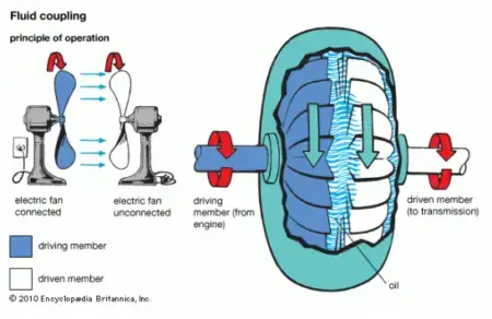
Your explanation using two fans to illustrate the working principle of a fluid coupling is a great way to conceptualize how a fluid coupling operates. It effectively demonstrates the basic concept of power transmission through a circulating fluid. Here’s a summary of the key points from your explanation:
- Two Fans Analogy: Imagine two fans placed close to each other, where one fan is connected to a power source (the powered fan), and the other is not connected to any power source (the unpowered fan).
- Initial Conditions: Initially, when the powered fan is running at a low speed, it doesn’t have enough airflow to drive the unpowered fan.
- Increasing Speed: As the speed of the powered fan increases, the airflow it generates also increases. This increased airflow starts to impact the blades of the unpowered fan.
- Transfer of Motion: The airflow from the powered fan transfers motion to the unpowered fan’s blades. Over time, as the speed of the powered fan continues to increase, the unpowered fan gradually accelerates until it reaches a similar speed to that of the powered fan.
- Fluid Coupling Analogy: This analogy illustrates the basic working principle of a fluid coupling, where the powered fan corresponds to the impeller in the fluid coupling, and the unpowered fan corresponds to the turbine. The impeller, driven by a prime mover (such as an engine or motor), circulates the fluid in the housing and imparts motion to the turbine, which eventually reaches a similar speed to the impeller.
Your explanation effectively captures the essence of how a fluid coupling uses a circulating fluid to smoothly transmit power from one shaft to another. It demonstrates how increasing the speed of the input (impeller) leads to the gradual acceleration of the output (turbine) until they achieve nearly equal speeds, all while avoiding abrupt starts and shocks. This is a fundamental concept in fluid coupling operation.
Fluid coupling working
A fluid coupling works based on the principles of hydrodynamics and the transfer of mechanical power through a circulating fluid. It is designed to smoothly and gradually transmit power from one shaft to another while providing certain benefits like overload protection and vibration damping. Here’s a step-by-step explanation of how a fluid coupling works:
- Components: A fluid coupling consists of two primary components enclosed within a sealed housing:
- Impeller (Driving Member): The impeller is connected to the input or driving shaft. It has blades or vanes that rotate with the input shaft.
- Runner (Driven Member): The runner is connected to the output or driven shaft and is positioned within the housing. It remains stationary during operation.
- Fluid Filling: The housing is initially filled with a specific type of viscous fluid, typically oil, up to a predetermined level, ensuring that both the impeller and runner are submerged in the fluid.
- Input Shaft (Driving Shaft): The impeller is connected to the input shaft, which is the shaft that receives the mechanical power from an external source, such as an engine or motor. When the input shaft rotates, it drives the impeller to spin with it.
- Creation of a Vortex: As the impeller rotates, it imparts kinetic energy to the fluid within the housing. The blades or vanes on the impeller create a centrifugal force that causes the fluid to move radially outward, creating a swirling or vortex motion within the housing.
- Interaction with the Runner: The swirling fluid within the housing interacts with the stationary runner, which is connected to the output shaft (driven shaft). The kinetic energy in the swirling fluid is transferred to the runner, causing it to rotate.
- Power Transmission: The runner, which is connected to the output shaft, transmits the mechanical power to the output shaft. This allows the output shaft to rotate at a speed proportional to the input shaft speed.
- Speed Control: The speed of the output shaft can be controlled by varying the speed of the input shaft. By adjusting the input shaft speed, the speed of the output shaft can be varied within certain limits, providing a degree of speed control.
- Overload Protection: One of the important features of a fluid coupling is its overload protection mechanism. If the load on the output shaft exceeds a certain limit, the fluid coupling starts to slip. This slip prevents excessive torque from being transmitted to the output shaft, protecting the machinery from damage due to overloading.
- Damping of Vibrations: Fluid couplings also have a damping effect on torsional vibrations and shock loads in the drivetrain. This helps reduce stress on connected equipment and contributes to smoother operation.
- Energy Dissipation: Some of the input energy is dissipated as heat due to the friction between the fluid layers during the circulation process. This heat dissipation helps maintain the operating temperature within acceptable limits.
In summary, a fluid coupling operates by creating a swirling motion of a viscous fluid within a sealed housing. This motion transfers mechanical power from the input shaft (impeller) to the output shaft (runner) in a gradual and controlled manner. The key advantages of a fluid coupling are its ability to provide smooth starts, controlled speed variations, overload protection, and vibration damping in a variety of industrial applications.
Fluid coupling function
A fluid coupling serves as a critical component in numerous industrial applications by facilitating smooth and controlled power transmission between rotating shafts. Its primary function lies in enabling the transfer of mechanical power from an input (driving) shaft to an output (driven) shaft without any direct physical contact between them. This seamless power transfer eliminates abrupt starts and shocks, safeguarding connected machinery from potential damage.
Fluid couplings also excel at providing overload protection, slipping when the load on the output shaft exceeds safe limits. Their ability to offer variable speed control within certain ranges is invaluable in scenarios where adjustable speeds are required. Furthermore, fluid couplings inherently dampen torsional vibrations and shock loads in the drivetrain, resulting in smoother operation and prolonged equipment life. Their continuous power transfer capability, heat dissipation function, and compatibility with harsh industrial environments make fluid couplings a dependable choice in various applications, ensuring efficient, reliable, and damage-resistant power transmission.
Application of fluid coupling
Fluid couplings are versatile mechanical devices used in a variety of industrial applications where controlled power transmission, torque multiplication, and speed control are required. Some common applications of fluid couplings include:
- Conveyors: Fluid couplings are widely used in conveyor systems to start and control the speed of the conveyor belts. They help prevent abrupt starts and stops, reducing wear and tear on the machinery and materials being transported.
- Mining Equipment: Fluid couplings are used in heavy mining equipment like conveyors, crushers, and draglines. They enable gradual acceleration of these machines, reducing stress on components and increasing operational efficiency.
- Pumps: Fluid couplings are employed in pumps to control the flow rate and prevent sudden pressure surges during startup. This is particularly important in water and wastewater treatment plants.
- Industrial Fans and Blowers: Large industrial fans and blowers often use fluid couplings to control the speed and reduce energy consumption during startup and operation.
- Crushers and Grinders: In industries like mining and aggregate processing, crushers and grinders use fluid couplings to smoothly start the equipment and manage torque, preventing motor overload.
- Marine Applications: Fluid couplings are used in marine propulsion systems, especially in ships with large engines. They allow for smooth and controlled engagement of the propellers, reducing wear on the drivetrain.
- Metal Rolling Mills: Rolling mills that shape metal sheets and bars use fluid couplings to control the speed and torque during the rolling process, ensuring precision and product quality.
- Paper and Pulp Industry: In paper and pulp mills, fluid couplings are used in various machinery, such as refiners and paper machines, to regulate speed and protect against sudden load fluctuations.
- Power Generation: It is used in power plants for various applications, including controlling the speed of fans, pumps, and generators.
- Agricultural Machinery: Some agricultural equipment, like grain augers and crop conveyors, utilize fluid couplings to manage the power transmission and protect against overloading.
- Automotive Testing: In automotive testing facilities, fluid couplings are used in dynamometers to simulate road conditions and test vehicle performance under controlled conditions.
- Oil and Gas Industry: It can be found in drilling equipment, compressors, and pumps in the oil and gas industry to regulate torque and prevent damage from sudden changes in load.
- Material Handling Equipment: Forklifts, cranes, and other material handling equipment use fluid couplings to provide controlled acceleration and deceleration, enhancing safety and efficiency.
These are just a few examples of the many applications of fluid couplings in industrial settings. Their ability to provide smooth and controlled power transmission makes them valuable components in various machines and systems across different industries.
Advantages of fluid coupling
Fluid couplings offer several advantages in industrial applications due to their unique design and operational characteristics. Here are some of the key advantages of using fluid couplings:
- Smooth and Gradual Startup: Fluid couplings provide a smooth and gradual startup, which helps reduce shock loads and stress on connected machinery. This feature is particularly important for equipment like conveyors, crushers, and pumps, where abrupt starts can cause damage and wear.
- Torque Multiplication: It can multiply torque, making them suitable for applications where higher torque is required during startup or operation. This can help overcome inertia and load resistance without overloading the driving motor.
- Overload Protection: It act as overload protection devices. When the load on the output shaft exceeds a certain limit, the fluid coupling will slip, preventing damage to the equipment. This feature is valuable in preventing costly breakdowns and downtime.
- Damping of Torsional Vibrations: It has a natural damping effect that helps absorb torsional vibrations and shocks in the drivetrain. This reduces the risk of damaging vibrations propagating through the system.
- Inherent Safety: It is inherently safe because they provide a controlled and slip-free power transmission without sudden jolts or jerks. This enhances operator safety and equipment longevity.
- Heat Dissipation: The circulating fluid in a fluid coupling helps dissipate heat generated during operation, preventing overheating and ensuring continuous operation even in high-load conditions.
- Low Maintenance: It has relatively low maintenance requirements compared to some other types of couplings or mechanical power transmission devices. They have fewer wear parts and do not require frequent lubrication or adjustments.
- Durability: Fluid couplings are robust and can operate in harsh environmental conditions, including dust, moisture, and extreme temperatures.
- Variable Speed Control: By controlling the speed of the input shaft, It can provide variable speed control at the output shaft, making them suitable for applications that require adjustable speeds.
- Energy Efficiency: While there are some energy losses due to fluid friction in fluid couplings, their smooth and controlled operation can actually help improve the overall efficiency of certain systems by reducing mechanical losses associated with abrupt starts and stops.
- Adaptability: It can be used in a wide range of applications across various industries. They can be customized and adjusted to suit specific requirements.
Despite their advantages, it’s worth noting that fluid couplings also have some limitations, such as energy losses due to fluid friction and heat generation. In some cases, other coupling types or variable frequency drives (VFDs) may be preferred for applications that require higher efficiency and precision speed control.
Disadvantages of fluid coupling
While fluid couplings offer several advantages in terms of torque multiplication, smooth power transmission, and overload protection, they also have some disadvantages and limitations that need to be considered for certain applications. Here are some of the disadvantages of fluid couplings:
- Energy Losses: Fluid couplings experience energy losses due to fluid friction and heat generation. This can result in reduced overall system efficiency compared to direct mechanical connections. In applications where energy efficiency is critical, other coupling types or variable frequency drives (VFDs) may be preferred.
- Limited Speed Control Range: It is not as versatile as VFDs in terms of precise speed control. While they can vary the output speed to some extent by changing the input speed, the control range may be limited compared to electronic control methods.
- Slip and Loss of Efficiency: Under certain operating conditions, especially when the load is significantly different from the design point, fluid couplings can experience slip, reducing their efficiency. This slip can lead to energy wastage and heat generation.
- Size and Weight: It can be relatively large and heavy, which can pose challenges in terms of installation and space requirements, especially in applications with limited space.
- Maintenance Requirements: While fluid couplings generally have lower maintenance needs compared to some other types of couplings, they still require periodic inspection and maintenance to ensure proper functioning. Over time, the fluid may need to be replenished or replaced.
- Cost: Fluid couplings can be more expensive upfront compared to some other coupling types. Depending on the application, the initial cost may be a consideration.
- Limited Precision: It may not provide the same level of precision in speed control as electronic systems like VFDs. In applications requiring extremely precise speed or torque control, other solutions may be more suitable.
- Temperature Sensitivity: Extreme temperature fluctuations can affect the performance of the fluid within the coupling. In very cold conditions, the fluid may become more viscous, affecting startup characteristics. Conversely, in high-temperature environments, the fluid’s viscosity may decrease, potentially reducing the efficiency of the coupling.
- Fluid Contamination: Contamination of the fluid within the coupling can lead to reduced performance and potentially damage the components. It’s important to ensure the fluid remains clean and free from foreign particles.
- Limited Reverse Operation: It is generally designed for one-directional power transmission and may not be suitable for applications that require frequent reversals in rotation.
Despite these disadvantages, fluid couplings remain valuable in many industrial applications, particularly where their advantages, such as smooth starting, torque multiplication, and overload protection, outweigh their limitations. The choice of coupling type should always depend on the specific requirements and constraints of the application.
Reference : https://en.wikipedia.org/wiki/Fluid_coupling