Inert Gas System on Ship – IG System Working & Components

Maintaining a safe atmosphere on ships is very important and Inert gas system on ships are fitted for the same reason. IG system on ship helps to maintain an inert atmosphere inside the cargo holds to avoid any explosion or accidents.

In order to understand the proper functioning on Inert Gas System, let’s clear out some basic terms which will be helpful in understanding the whole process.

What is Inert Gas ?

An Inert gas is a gas which does not take part in chemical reaction under a given set of conditions.

In simple language, Inert gas is the gas which contains insufficient oxygen ( Normally, less than 8 percent ) to prevent or avoid combustion of flammable gases.

What is IG System or Inert Gas System on Ship ?

An Inert Gas System installed on a tanker is designed to prevent explosion in a tanker’s cargo tank by maintaining a non-explosive atmosphere inside the tank by reducing the oxygen limit inside the space insufficient to cause explosion.

It is used for safe operation of ship so, Gas freeing must be carried out subsequently if workers have to enter the empty tanks.

Inert Gas System Diagram

Image of I.G System
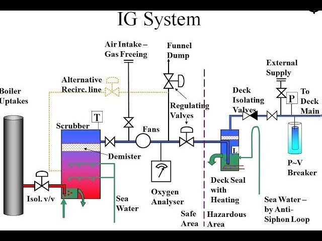
Inert Gas system

As we know that fire needs oxygen, heat, and fuel to burn. If we remove One of the elements of the fire triangle, we can prevent fire.

Principle of Inert Gas System on Ships

The basic principle of inert gas system is to remove the oxygen content by introducing inert Gas to any compartment that contains a mixture of hydrocarbon gases.

Thus, system minimize the risk of explosion.

The inert gas system delivers inert gas over the oil cargo hydrocarbon mixture, increasing the LEL lower explosion limit (lower concentration at which vapours can be ignited) while decreasing the higher explosion limit HEL (Higher concentration at which vapour explodes).

When the concentration reaches around 10%, an atmosphere inside the tank is created in which hydrocarbon vapours cannot burn. As a safety precaution, the concentration of inert gas is kept at around 5%.

What is The Purpose of The Inert Gas System on Ship ?

Oil tankers transport oil of various grades and quality, which has the ability to produce flammable vapours and gases when loaded for transportation. Even though there is no cargo on board, there may be dangerous flammable gases available in the hold.

When the vapour produced by an oil cargo is mixed with a specific concentration of air primarily containing oxygen, an explosion can occur, resulting in property damage, marine pollution, and loss of life.

Onboard, an inert gas system is used to protect against such explosions. A separate inert gas plant or flue gas produced by a ship’s boiler can be used. Inert gas systems are used for preventing the formation of flammable conditions inside spaces containing a flammable product, such as the vapour space of storage tanks.

Working of Inert Gas System
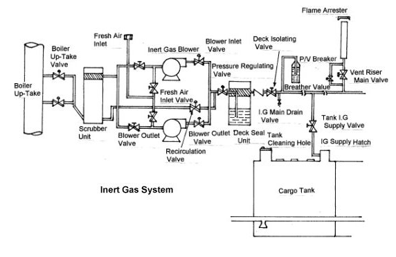
Inert Gas System
  • Hot Flue gases from the exhaust of Boiler is taken to the bottom of the scrubber tower through the boiler uptake valve.
  • In the scrubber tower, Flue gases are passes through a series of water spray and baffle plates to cool, clean, and moisten the gases. The SO2 level drops by up to 90% and the gas becomes soot-free.
  • The flue gas come out from the scrubber tower is free from shoot and So2.
  • But it contains moisture. So, it is then passed through a demister to remove moisture before leaving to suction of the blower.
  • The treated gas is delivered to the tanks by motor-driven inert gas blowers from the scrubber tower. They are supported by rubber vibration absorbers and are separated from the piping by rubber expansion bellows.
  • The gas control valves ( pressure regulating valve ) regulate the amount of gas delivered to the deck, and the pressure controller controls the deck pressure. If the deck pressure is lower than the set point, the output signal will be raised to increase the opening of the valve, and vice versa if the deck pressure is higher than the set point. These valves will then work together to maintain both the deck pressure and the blower pressure at their respective setpoints without starving or overfeeding the circuit.
  • The gas passes through the deck water seal before entering the deck line, which also acts as a non-return valve, preventing the back-flow of explosive gases from the cargo tanks.
  • After the deck seal, the inert gas relief is fitted to balance built-up deck water seal pressure when the system is shut down. In conditions of a failure of both the deck seal and the non-return valve, the relief valve did the work of venting the gases flowing from the cargo tank into the atmosphere.
  • The oxygen analyzer is fitted after the blower. It separates the production and distribution components of the plant.
  • It analyzes oxygen content in the gas and if it is more than 8 percent, alarms activated and shutdown the plant.

Inert Gas System Components with Description

1. Exhaust Gas Sources :- The source of Inert gas is a.) Exhaust Uptake of Boiler and b.) Exhaust Uptake of Main engine. It is because Exhaust gas contains flue gases in it.

2. Inert Gas Isolating Valve :- As the name suggest, it isolate the System from the exhaust uptake.

3. Scrubbing Tower :- The flue gas enters the scrubbing tower from the bottom and passes through a series of water spray and baffle plates to cool, clean, and moisten the gases. The SO2 level drops by up to 90% and the gas becomes soot-free.

4. Demister :- A  demister is a device often fitted to vapor–liquid separator vessels to enhance the removal of liquid droplets entrained in a vapor stream.

Here, it is used for absorbing moisture and water from the treated flue gas. Generally, it is made up of polypropylene.

5. Gas Blower :- Typically, two types of fan blowers are used: a steam-driven turbine blower for I.G operation and an electrically driven blower for topping off.

6. I.G pressure Regulating valve :- The pressure within the tanks varies depending on the oil’s properties and the atmospheric conditions. To control this variation and prevent the blower fan from overheating, a pressure regulator valve is attached after blower discharge, re-circulating the excess gas back to the scrubbing tower.

7. Oxygen Analyzer: It is a device fitted after the pressure regulating valve. If the oxygen level is more than 8% by volume, it will sound an alarm and release inert gas to the atmosphere.

8. Deck seal :- The deck seal’s purpose is to prevent gases from returning from the blower to the cargo tanks. Generally, Deck seals of the wet type are used. To absorb the moisture carried away by the gases, a demister is installed.

9. Mechanical Non return valve :- It is an additional non-return mechanical device in line with the deck seal.

10. Deck Isolating Valve : – This Valve is used for Isolating engine room system Fully with deck system.

11. Pressure Vacuum breaker :- The PV breaker valve used for controlling the over or under pressurization of the cargo tank. The PV breaker vent is equipped with a flame trap to prevent a fire from igniting while in port during loading or discharging operations.

12. Cargo Tank Isolating Valve :- A vessel has a number of cargo holds, each of which has an isolating valve. The valve regulates the flow of inert gas to hold and is only operated by a responsible officer on board.

13. Mast Riser :- Mast riser is used for maintaining a positive pressure of inert gas at the time of loading of cargo and during the loading time it is kept open to avoid pressurization of the cargo tank.

14. Safety and Alarm Systems :- The Inert gas system is fitted with safety and alarm system for safe operation of ship.

Alarms and Systems Fitted in IG System

  1. A. A high level in the scrubber raises an alarm, allowing the blower and scrubber tower to shut down.
  2. Low-pressure seawater supply to the scrubber tower (approximately 0.7 bar) causes an alarm and shutting down of blower.
  3. A low pressure seawater supply (approximately 1.5 bar) to the deck seal causes an alarm and the blower to shut down.
  4. High inert gas temperature (approximately 70 degrees Celsius) causes an alarm and the blower to shut down.
  5. Low pressure in the line after the blower (approximately 250mm wg) causes an alarm and the blower to shut down.
  6. A high oxygen content (8%) causes an alarm and the shutdown of gas delivery to the deck.
  7. A low level in the deck seal causes an alarm and the gas supply to the deck to be cut off.
  8. Power failure leads to alarm and shutdown of blower and scrubber tower
  9. An emergency stop causes an alarm and the blower and scrubber tower to shut down.

Inert Gas Plant Alarms

The various alarms incorporated in the Inert Gas plant are following :-

A. Scrubber low level
B. Deck seal High level
C. Low O2 Content (1%)
D. High O2 Content (5%)
E. Low lube oil pressure alarm

Inert Gas System Starting Procedure

Onboard, careful consideration is required for the inert gas system to function properly. The oxygen content must always be kept at 5% by volume; any further reduction in oxygen content will result in the mixing of impurities in the gas, which will be difficult to separate. Before starting the inert gas system, certain precautions must be taken.

  1. Open the valve related to the burner of fuel and check Fuel is adequate or not for operation of Boiler and Inert gas generator.
  2. Switch on the electric power of Control panel.
  3. The scrubber’s water drain lines must be opened.
  4. Check and ensure that the oxygen analyzer is working properly and required then calibrate.
  5. Set pressure control setting for inert gas in distribution lines.
  6. Set the pressure control valve of the burner.
  7. Ensure supply of sea water to the deck seal.
  8. Check and ensure that The system lines are lined up.
  9. Before entering the port, start the inert gas generator. (Actually, this is done to avoid dark black smokes from coming out when it starts.)

Inert Gas System Starting Procedure

  1. Follow all the I.G system checklist as per guidelines of company.
  2. Check and ensure that all cargo openings are closed.
  3. Prior to start, line up the system properly.
  4. Take the precautionary measure mentioned above.
  5. Start the IG system
  6. Check the oxygen analyser readings.
  7. Supply inert gas to the Deck opening Inert gas main supply valve.
  8. Keep an eye to the all Pressure parameters.
  9. During cargo Operations, Monitor the temperature and the oxygen level of inert gas.
  10. Increase the pressure of inert gas before stopping the inert gas plant.

Also Read : Steering Gear
Oily Water Separator on Ships
Fresh Water Generator
Centrifugal Pump Parts Working Diagram
Heat Exchanger Types Working Principle

What is the purpose of inert gas?

Inert gases are commonly used to prevent unwanted chemical reactions from degrading a sample. These unfavourable chemical reactions are frequently oxidation and hydrolysis reactions with air’s oxygen and moisture.
Inert gases are also used to remove oxygen from confined spaces where combustible gases are present, such as certain sewers.

Which inert gas systems use only gases from the ship’s main or auxiliary boiler?

The flue gas plant.

How is the inert gas fed into cargo tanks?

Process used for Inerting is Displacement Method.
The displacement method differs slightly from the dilution method. The inert gas is used to displace the air inside the tank in this method. With this method, close to one air change is required to achieve less than 8% oxygen from an initial 21%.

What are the 7 inert gases?

1. Helium (He)
2. Neon (Ne)
3. Argon (Ar)
4. Krypton (Kr)
5. Xenon (Xe)
6. Radon (Rn)
7. Oganesson (Og)

Check Out Other Important Topics

IC EngineImportant PDFsBoilersSynergy Maritime ExamNaval ArchMEO Class 4
Interview QuestionsDifference BetweenTypes of PumpsAuxiliary MachinesTypes of ValvesHome


Colour Code of Pipe Used on Ship

Colour Code of Pipe Used on Ship

Pipes on ships are color-coded to ensure safety, facilitate maintenance, and prevent accidents. These codes help crew members quickly identify the contents of each pipe and take appropriate precautions. The International Maritime Organization (IMO) has established standard color codes that shipbuilders and operators must follow.

Common Color Codes:

  1. Blue: Freshwater systems
  2. Green: Seawater
  3. Yellow: Fuel oil
  4. Brown: Sewage
  5. Red: Firefighting systems
  6. Orange: Hydraulic oil
  7. Gray: Air systems

These standardized codes help streamline operations, increase safety, and ensure clear communication among crew members, especially during emergencies.

Importance of Pipe Color Coding

  • Safety: Quickly identifying dangerous or hazardous fluids.
  • Maintenance Efficiency: Speeding up repairs by immediately identifying systems.
  • Accident Prevention: Avoiding cross-contamination between pipes and systems.

Understanding the IMO Guidelines

While the color codes listed above are commonly used, the IMO (International Maritime Organization) and ISO (International Standards Organization) have specific guidelines that ships must follow. These guidelines cover not only the color but also additional markings that help to indicate the type of liquid or gas flowing through the pipe.

For example, pipes that carry seawater might not only be colored green but also have arrows or stripes showing the direction of flow. Some pipes may have alphanumeric codes or other identification marks that clarify the type of fluid they carry, such as “FO” for fuel oil or “SW” for seawater.

Breakdown of Common Pipe Systems on Ships

  1. Freshwater Systems: Identified by blue, freshwater pipes supply potable water for crew and passengers. These pipes run to sinks, showers, and drinking water outlets.
  2. Seawater Systems: Green indicates seawater used for various functions like cooling, firefighting, or ballast water. These pipes need to be clearly marked to prevent mixing with freshwater systems.
  3. Fuel Systems: Yellow identifies fuel oil pipes. Proper marking is critical to prevent the accidental mixing of fuel with other fluids, which could lead to engine failure or safety hazards.
  4. Sewage Systems: Brown pipes indicate sewage, directing wastewater to holding tanks or treatment plants. Proper identification prevents cross-contamination and ensures hygiene standards are maintained.
  5. Firefighting Systems: Red pipes are used exclusively for firefighting water systems and other fire suppression systems, such as sprinklers or CO2 systems.
  6. Hydraulic Oil Systems: Orange pipes indicate hydraulic oil used in systems that control mechanical operations, such as cargo winches or steering gear.
  7. Air Systems: Gray marks pipes carrying air, such as those supplying compressed air for machinery or tools.

Additional Markings for Clarity

In addition to color coding, pipes may have additional markings for enhanced clarity:

  • Direction arrows: Indicate the flow direction of liquids or gases.
  • Stripes or bands: Provide more detailed identification within a system (e.g., potable vs. non-potable freshwater).
  • Text labels: For further clarity, especially in complex systems.

Conclusion

Using a color-coded system for pipes on ships is essential for efficient operations and safety. These codes provide clear visual identification, helping crew members handle different systems without confusion. Following the IMO guidelines ensures international standardization and compliance with safety regulations, minimizing the risk of accidents and ensuring smooth ship operations.

Propeller Drop

What is Propeller Drop?

Propeller Drop refers to the vertical movement or drop of the propeller shaft due to the combined effects of the propeller’s weight and the wear that occurs in the bearings that support the shaft. Over time, as the bearing wears down, a small clearance develops, causing the shaft to sink slightly. This sinking or drop is measured and referred to as propeller wear down or propeller drop.

Must Read : Rudder Drop

How is Propeller Drop Measured?

Propeller drop is typically measured using a poker gauge during a dry dock maintenance period. A dry dock is a period when the ship is taken out of water to inspect and perform maintenance on the hull and propeller, among other parts.

Detailed Explanation

The propeller shaft is a long cylindrical piece of metal that connects the ship’s main engine to the propeller. One end is fixed to the engine, and the other end is attached to the propeller. Because the propeller is heavy and rotates in water, it tends to exert a downward force on the shaft over time, especially as the bearings supporting the shaft wear down.

To prevent sea water from entering the engine room, the propeller shaft passes through seals when it exits the hull. These seals are usually located in the aft peak tank and are called lip seals. They are made from materials like nitrile rubber or viton, which press tightly against the shaft’s bronze liner to create a waterproof seal.

Over time, grooves may form on the shaft’s liner surface due to the wear of these seals, allowing water to seep through. This reduces the lubrication between the liner and the seals, causing wear on the propeller shaft.

As the wear increases, the propeller shaft begins to sink under its weight, creating a clearance between the shaft and its bearings. This clearance, or drop, is the propeller drop.

Precautions Before Measurement:

  • Rope Guard: Before measuring the propeller drop, the rope guard (a protective cover) around the propeller needs to be removed.
  • Poker Gauge Availability: Ensure that the vessel has a poker gauge, the specialized tool used to measure the drop.

Procedure for Measuring Propeller Drop:

  1. Position the Gauge: The poker gauge is inserted between the last and second-to-last seals in the stern tube (near the propeller).
  2. Plug Removal: A plug on top of the seal is removed to allow the poker gauge to be inserted.
  3. Taking the Measurement: The poker gauge measures how much the shaft has dropped due to wear in the bearing.
  4. Comparison: The measurement is taken at each dry dock, and readings are compared to previous records to monitor the progression of wear.

Instruments Used to Measure Propeller Drop:

  • Poker Gauge: The most commonly used tool to measure propeller drop.
  • Other tools like filler gauges or vernier calipers may also be used, but the poker gauge is specialized for this measurement.

Common Procedures for Stern Tube Wear-Down Measurement:

  • Use of Poker Gauge: Insert the poker gauge or wear down gauge into the stern tube, after removing the rope guard and plugs.
  • Mark Alignment: Align the tail shaft’s zero marks with the Simplex seal and stern tube.
  • Reading: Take the top and bottom measurements and compare them with previous dry dock records to determine the wear progression.

How to Read a Poker Gauge?

The poker gauge provides a direct reading of the shaft drop. By comparing this reading with previous values, you can assess how much the shaft has worn down and whether maintenance is required.


This explanation covers the basics of propeller drop, its causes, and how it is measured. Let me know if you need further clarification on any part!

Centrifugal Pump : Types, Diagram, Working Principle

Centrifugal pumps are widely used in various industries to transport fluids from one place to another. These pumps work on the principle of converting mechanical energy into hydraulic energy, which is then used to move the fluid. In this article, we are going to discuss different types of centrifugal pumps, their diagrams, and the working principle that makes them so effective.

We will also discuss what are the advantages and disadvantages of using centrifugal pumps and what are the applications of centrifugal pumps in various industries.

Pump – A pump is a mechanical device which helps in transferring a fluid from one place to another by increasing its pressure.

What is Centrifugal Pump ?

Centrifugal Pump is a type of Rotodynamic pump in which the flow through the pump is induced by the centrifugal force imparted to the liquid by rotation of the impeller.

The centrifugal Pump operates on a rotodynamic principle in which the flow through the Pump is induced by the centrifugal force imparted to the liquid by the rotation of an impeller. Therefore it is also known as Rotodynamic Pump.

Parts of Centrifugal Pump

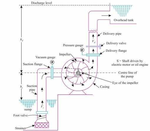
The main parts of centrifugal pump are:

Impeller

The impeller is the one whose rotary motion induce a centrifugal force on the fluid. The rotational components of centrifugal pump are called impellers. A shaft that is attached to an electric motor has an impeller placed on it. The impeller is rotated by the motor.

They are made of a collection of backward-curving blades and come in various sizes and forms to suit different applications and the characteristics of the pumped liquids. Depending on the chemical characteristics of the liquid being pumped, a variety of materials can be used to make the impellers. Before being put on the pumps, all impellers must be dynamically balanced.

Shaft

The impeller is mounted on a shaft and enclosed by casing. The impellers, shaft sleeves, and bearings are positioned on the shaft of a centrifugal pump, which is the central portion of the rotor. The shaft receives mechanical energy from the motor. The impeller rotates with the help of the shaft.

Casing

Casing is the stationary part of the centrifugal pump which acts as housing to all the internal parts and protects them from external atmosphere. This is an airtight passage that surrounds the impeller. It is constructed in such a manner that, before the water exits the casing and enters the delivery pipe, the kinetic energy of the water is converted to pressure energy. The casing converts velocity imparted by impeller to the water in a steady flow.

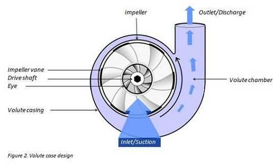
Volute Casing

This is so named because of its spiral shape which is so constructed to convert the part of the velocity of the fluid to the pressure energy, which is the objective of a pump , to increase the fluid’s pressure.

Some of the centrifugal pump also uses diffuser in addition to the volute casing.

Diffuser in a centrifugal pump

The diffuser performs the same function as volute casing i.e. convert part of K.E energy of the fluid to the pressure energy. It consists of a ring of guide passages around the impeller. This design is used for high pressure as in multi-stage boiler feed pump.

The diffuser-type casing’s construction enables water exiting the impeller to enter the guiding blades shock-free. The area of water flowing between the blades increases, slowing the flow rate and raising the pressure of the fluid. After the guide blades, water passes through the surrounding casing which is typically kept concentric with the impeller.

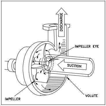
Eye Of The Impeller

In the centre of the centrifugal pump impeller, is the eye of the impeller which receives inlet flow of liquid into the vanes of the impeller.

Suction Pipe with Foot Valve And Strainer

A pipe whose one end is connected with the inlet of the impeller and the other end is dipped into the sump of the water is called suction pipe. The suction pipe consists of a foot valve and strainer at its lower end. The foot valve is a one way valve that opens in the upward direction so that the water does not flow back to the supply side when the pump is not in the operation. The strainer is used to filter the unwanted particles present in the water to prevent the centrifugal pump from blockage.

Bearings in Centrifugal Pump

The purpose of the bearings is to maintain the shaft or rotor’s proper alignment with the stationary components when radial and axial loads are applied. The two different types of Bearings are used used in centrifugal pump are Line Bearings and Thrust Bearings. Line bearings provide radial positioning to the rotor while Thrust bearings place the rotor in axial position. In many cases, the thrust bearings function as both thrust and radial bearings.

Sealing Arrangements

As the spinning shaft travels through the stationary casing of the centrifugal pump, the sealing arrangement is a component that seals the shaft. It limits the amount of fluid leakage into the atmosphere or the entry of outside air while reducing the wear on the sealing faces.

Delivery Pipe

Delivery pipe is the pipe whose one end is connected to the outlet of the pump and the other end is connected to the required height where water is to be delivered.

Also Read : Difference Between 2 Stroke and 4 Stroke Engine

Centrifugal Pump Working Principle

The working principle of a centrifugal pump involves the conversion of mechanical energy into hydraulic energy, which is then used to move the fluid.

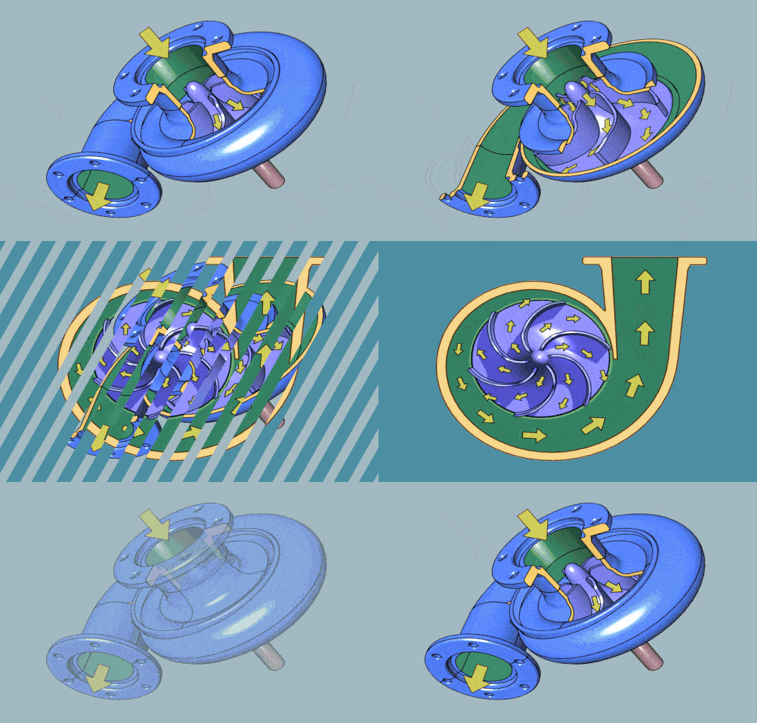
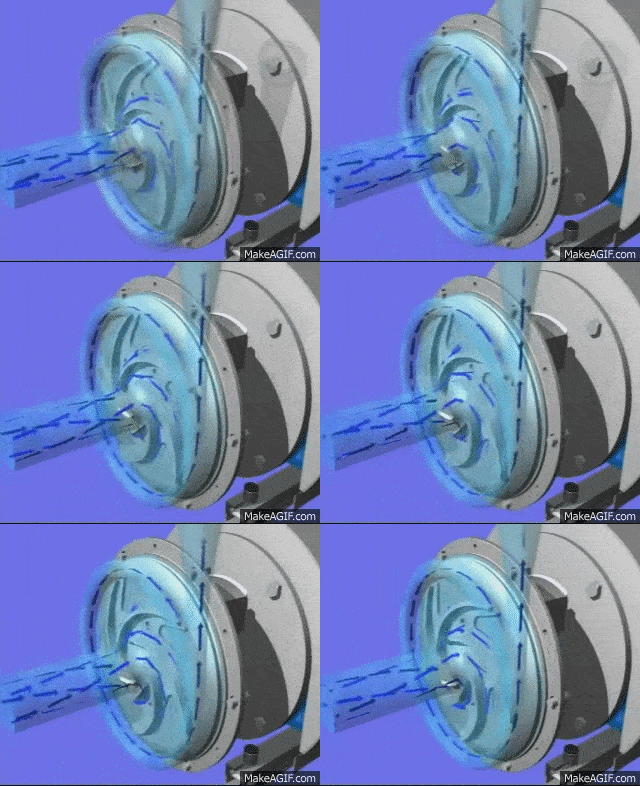
The rotation of the centrifugal pump impeller causes the liquid it contains to move outward from the center to beyond the circumference of the impeller because of the centrifugal effect. And because of this movement of the fluid to the outer periphery, there is a drop of pressure at the eye of the impeller. This drop in pressure creates the suction force of the pump and hence the pump draws the fluid from the suction supply.

Now, the water due to centrifugal force continue to move towards the casing. The area of casing increases gradually in the direction of rotation. So the velocity of the water keeps on decreasing and the pressure increases and at the outlet of the pump the pressure is maximum. From the outlet of the pump, the water goes to its desired location through delivery pipe.

Overall, the working principle of a centrifugal pump involves the creation of a low-pressure zone at the center of the impeller, the transfer of kinetic energy from the impeller to the fluid, and the conversion of kinetic energy into pressure energy through the volute casing.

Centrifugal pump diagram

Working of Centrifugal Pump : Detailed Explanation

Read More : What is Caustic Embrittlement ?

Priming of Centrifugal Pump

One important thing is to note that the centrifugal pump is not self-priming. So in order to make it functional it needs to be primed.

What is meant by priming in centrifugal pump?

Priming is the process in which the suction pipe , casing, and delivery pipe up to the delivery valve is filled completely with liquid to be raised, from outside source before starting the pump.

Why does a centrifugal pump need priming?

Priming of centrifugal pump is done to remove the air from the pump. If the air is not removed from the pump then only a small negative pressure is created at the suction pipe and it cannot suck the water from the water sump.

Types of Centrifugal Pumps

Centrifugal Pumps are classified into many types based on many categories, they are

Based on number of impellers in the pump,

  1. Single stage pump
  2. Two-stage pump
  3. Multi-stage pump

Based on orientation of case-split,

  1. Axial split Pump
  2. Radial split Pump

Based on type of impeller design,

  1. Single suction Pump
  2. Double suction Pump

Based on the basis compliance with industry standards,

  1. ANSI pump – (American National Standards Institute)
  2. API pump – (American Petroleum Institute)
  3. DIN pump – DIN 24256 specifications
  4. ISO pump – ISO 2858, 5199 specifications
  5. Nuclear pump – ASME (American Society of Mechanical Engineers) specifications

Based on type of volute

  1. Single volute Pump
  2. Double volute Pump

Based on where the bearing support is,

  1. Overhung
  2. Between-bearing

Based on on shaft orientation

  1. Horizontal Pump
  2. Vertical Pump

What are the Advantages of Centrifugal Pump?

The centrifugal pump has following advantages:

  • Multiple uses: Centrifugal pumps are frequently employed in a variety of processes, including the provision of water, the treatment of wastewater, chemical processing, and the manufacture of petroleum.
  • Simple design: Centrifugal pumps have a straightforward design that makes them simple to use, maintain, and fix.
  • High flow rates: Centrifugal pumps are suitable for many industrial applications because they can handle enormous volumes of fluid at high flow rates.
  • Energy efficiency: Centrifugal pumps typically use less energy than other types of pumps, which over time can save you a lot of money.

What are the Disadvantages of Centrifugal Pump?

The centrifugal pump has following disadvantages:

  • Limited suction lift: Centrifugal pumps may not be able to raise fluids from deeper levels due to their limited suction lift.
  • Poor performance when pumping viscous fluids: Because of the high velocity of the fluid and the potential for aerated or frothy fluid, these pumps are not recommended for pumping viscous fluids, such as oils or syrups.
  • Reduced efficiency at low flow rates: This could lead to increased energy expenses when it experiences reduced efficiency at low flow rates.
  • Cavitation risk: Cavitation, which happens when the pressure inside the pump falls below the vapour pressure of the fluid, can potentially harm centrifugal pumps by causing bubbles to form.

Why start centrifugal pump with discharge closed?

By closing the discharge valve, we can reduce the starting current.

As we know that, the current will be high during the starting of any motor. If we start the pump with the discharge valve open, The discharge head will act on the pump i.e. more resistance, so the motor has to give more starting torque to the pump which means more current is drawn by the motor.

In other words, if there is pressure in discharge side of the pump , prior to startup, it can flow back through the pump, causing a backward spin and may draw more current, thereby causing damage to the pump.

Centrifugal-Pump-Working

Suggested Read : Easiest Method To Calculate Brake Horse Power

Cavitation in Centrifugal Pump

During operation if the drop in the pressure created at the suction side of a centrifugal pump (by liquid moving radially outwards from the eye of the impeller) is greater than the vapor pressure for the temperature at which liquid being pumped, the vapor / bubbles will be drawn from the liquid in this area.

Any vapour bubbles formed by the pressure drop at the eye of the impeller are swept along the impeller vanes by the flow of the liquid. When the bubbles enter from low pressure to high pressure farther out the impeller vanes, they abruptly collapse. The process of the formation and subsequent collapse of the vapor bubbles in a pump is called cavitation.

This phenomenon is likely to occur if there is a restriction in the suction pipe, or if the liquid is volatile, or has a higher temperature than anticipated, or if the impeller speed is excessive.

Cavitation degrades the performance of the pump, resulting in a fluctuating flow rate and discharge pressure. It can also be destructive to the pump’s components as collapsing of bubbles on impeller vanes can damage the blades. It can also cause excessive pump vibration which could damage pump bearings, wearing rings and seals.

Centrifugal-Pump

Read About : Bulwark Definitions Meaning

Net Positive Suction Head

It is the difference between inlet pressure and the lowest pressure level inside the pump. It is therefore an expression of the pressure loss that takes place inside the first part of the pump housing.

Required NPSH is the lowest inlet pressure required by the specific pump at a given flow to avoid cavitation.

Available NPSH is the absolute pressure at the suction part of the pump.

Pump will operate only if:

( required NPSH > Available NPSH )

Vapour Pressure

It refers to the pressure at which the vapour and liquid phases are in equilibrium .

Suction Lift

Suction lift exists when the source of supply is below the center line of the pump. Thus, static suction lift is the vertical distance from the center line of the pump to the free level of the liquid to be pumped.

Suction Head

Suction Head exists when the source of supply is above the center line of the pump. Thus, static suction head is the vertical distance from the centerline of the pump to the free level of the liquid to be pumped .

Static Discharge Head

It is the vertical distance between the center line and the point of free discharge or the surface of the liquid in the discharge tank.

Total Static Head

It is the vertical distance between the free level of the source of supply and the point of free discharge or the free surface of the discharge liquid.

Friction Head

It is the head required to overcome the resistance to flow in pipe and fittings. Depends on the size, type of pipe, flow rate and the nature of the liquid.

Some Other Topics : What are the various Boiler Mountings ?

Crankcase Explosion – Occurrence, Prevention, Precautions

FAQs : Centrifugal Pump

What is centrifugal pump and how it works?

It is a device which is used to transfer Liquid From suction to discharge with the help of rotational energy. The centrifugal Pump operates on a rotodynamic principle.

What are the 3 types of centrifugal pumps?

1. Single Stage
2.Two-stage
3. Multi-stage

What does a centrifugal pump do?

It is a mechanical device which is used for transfer liquids from one place to another by increasing its pressure.

What is priming of a pump?

Priming is the process in which the suction pipe , casing, and delivery pipe up to the delivery valve is filled completely with liquid to be raised, from outside source before starting the pump.

What is centrifugal pump used for?

Centrifugal pumps are widely used for fluid transport in a wide range of industries including wastewater treatment, water supply, chemical processing, oil and gas transport, food and beverage processing and HVACs systems.

Which motor is used in centrifugal pump?

DC shunt motor because it runs at constant speed. As a result, it is employed for operating centrifugal pumps, lathes, constant speed line shafts, tiny printing presses, and other machinery.

What is difference between pump and centrifugal pump?

A pump is a device used to move fluids (liquids or gases) from one place to another, while a centrifugal pump is a specific type of pump that uses a rotating impeller to increase the velocity of a fluid and then transfer it to a another location.

Essentially, all centrifugal pumps are pumps, but not all pumps are centrifugal pumps. Other types of pumps are positive displacement pumps, axial flow pumps, and mixed flow pumps.

Why is it called centrifugal pump?

The term “centrifugal” in the name of the pump refers to the centrifugal force that is generated by the rotation of the impeller. Rotation of the impeller creates a centrifugal force that creates a pressure differential, which in turn causes the fluid to move through the pump and out of the discharge port.

Check Out Other Important Topics

IC EngineImportant PDFsBoilersSynergy Maritime ExamNaval ArchMEO Class 4
Interview QuestionsDifference BetweenTypes of PumpsAuxiliary MachinesTypes of ValvesHome

Hydrophore System

What is Hydrophore System on ship ?

hydrophore system : It is a type of water supply system that uses a pressure tank to store water under pressure, providing a consistent water supply to the multiple areas of the vessel at distinct heights in all lines and on all vessel floors.

You Should read about fresh water generator

Why is hydrophore System on board compulsory?

The Hydrophore System is an essential component on board vessels for maintaining a stable and efficient freshwater supply. Here’s why it is compulsory:

1. Stabilizes Water Pressure:

On vessels, freshwater demand varies greatly across different areas such as cabins, galleys, and machinery spaces. Without a hydrophore system, directly using a pump would cause constant pressure fluctuations, especially during periods of low water consumption. The hydrophore system provides a pressurized reservoir that maintains system pressure within a specific range, ensuring stable water supply despite changes in demand.

2. Reduces Pump Cycling:

A centrifugal pump connected directly to the freshwater line would frequently turn on and off (cycle) due to fluctuating demand. This frequent cycling leads to wear and tear on the pump, reducing its lifespan and efficiency. The hydrophore system acts as a buffer, reducing the need for the pump to start and stop frequently, thereby preventing excessive cycling and extending the pump’s lifespan.

3. Ensures Consistent Supply:

The system provides compressed air assistance to pressurize the water supply, ensuring that all areas of the ship have access to consistent water pressure, regardless of the number of users. This is critical for areas like showers, sinks, and machinery that require constant water flow for proper functioning.

4. Increases System Efficiency:

By maintaining constant pressure and reducing the strain on the pump, the hydrophore system helps in optimizing the efficiency of the entire freshwater distribution system on board. This leads to less energy consumption, lower maintenance costs, and smoother operation.

5. Protects the Plumbing System:

The hydrophore system acts as a buffer, preventing pressure surges that could damage the plumbing lines, fixtures, and fittings. This makes it a crucial component in protecting the integrity of the vessel’s freshwater distribution system.

Conclusion: The hydrophore system is compulsory on vessels because it ensures reliable water pressure, prevents pump overuse, maintains system efficiency, and protects the vessel’s plumbing infrastructure from damage due to fluctuating demand. This makes it a vital part of the ship’s water management system.

Working of Hydrophore System

Hydrophore System On Ship

Working of the Hydrophore System:

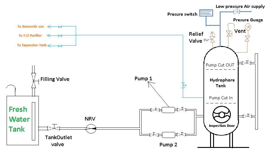
The hydrophore system provides a consistent and reliable water pressure for various systems on board, such as freshwater supply, fire lines, and sprinkler systems. The system leverages the fact that while water cannot be compressed, air can be, offering a smart solution for maintaining stable pressure without constant pump operation.

Here’s a step-by-step breakdown of how the hydrophore system works:

  1. Water and Air Interaction:
  • The hydrophore tank contains both water and compressed air. Since water cannot be compressed, the pressure regulation is achieved by compressing the air in the tank, which, in turn, pressurizes the water inside.
  • As the tank is filled with water, the air is compressed, building up the required pressure in the system.
  1. Pump Operation:
  • A pump fills the hydrophore tank with water. Once the water reaches a certain level and the air is compressed to a preset pressure, the pump turns off.
  • The compressed air now acts as a cushion, pressurizing the water, allowing it to be distributed throughout the ship without the need for the pump to be constantly running.
  1. Pressure Regulation:
  • As water is consumed or used in different parts of the ship, the air expands, maintaining the pressure within the system. The system can supply water to various outlets like sinks, showers, or fire lines, all at consistent pressure, without having to constantly restart the pump.
  • When the water level in the tank drops to a certain point, and the air pressure begins to fall below a set limit, the pump reactivates, refilling the tank with water, compressing the air again.
  1. Avoiding Constant Pump Cycling:
  • Without a hydrophore system, the pump would have to cycle frequently to maintain pressure, especially during low water demand periods. This cycling leads to excessive wear and tear on the pump.
  • By using the air-water balance in the hydrophore tank, the system avoids the need for constant pump activation, ensuring the pump operates less frequently, leading to increased pump longevity and system stability.
  1. Consistent Water Pressure:
  • The compressed air in the hydrophore system allows for consistent water pressure across the system, even with fluctuating water demands. Whether the demand is high or low, the system maintains a steady pressure, ensuring all areas of the ship receive the required water pressure for efficient operation.

Advantages of the Hydrophore System:

  • Prevents pump wear and tear by reducing the need for frequent cycling.
  • Maintains stable pressure in systems like freshwater lines, fire suppression, and sprinklers.
  • Efficient use of energy, as the pump runs less frequently, only when the tank needs to be refilled.
  • Reduces pressure fluctuations, ensuring a smooth and reliable water supply.

Charging of Hydrophore System

Charging of the Hydrophore System:

Charging a hydrophore tank is essential to ensure the proper balance of air and water for maintaining stable pressure. The process involves adding compressed air to the tank after filling it with water, which helps pressurize the system. Here’s a step-by-step guide:


Steps to Charge the Hydrophore System:

  1. Release Existing Pressure:
  • Open the vent to release any air or pressure that may already be in the hydrophore tank. This ensures you start with a tank that is ready to be filled and charged.
  1. Fill the Tank with Water:
  • Start the pump to begin filling the tank with water.
  • Monitor the sight glass to see the water level. Fill the tank until it reaches about 70% capacity. This leaves space for the air to be compressed, which is necessary for pressurizing the system.
  1. Close the Vent:
  • Once the tank is filled to the desired level, close the vent to seal the system and prevent further air from escaping.
  1. Add Compressed Air:
  • Open the valve for low-pressure air supply to begin adding compressed air to the hydrophore tank.
  • Quickly charge the tank to 4.5 bar air pressure. This initial pressurization ensures the system starts operating at a safe pressure level.
  1. Gradually Increase Pressure:
  • Gradually increase the air pressure to reach 5 to 5.5 bar, or the level recommended by the manufacturer. Be cautious to avoid over-pressurizing the system, which could cause problems, such as excessive water coming out of the taps.
  1. Monitor the Water Level:
  • Ensure there is always water visible in the gauge glass during operation. This indicates that the balance between air and water is being maintained correctly.
  1. Transfer the System to Auto Mode:
  • Once the tank is properly charged, switch the system to auto mode.
  • In this mode, the pump will:
    • Cut in (start) at 4.5 bar (or 2.5 bar in smaller vessels or industries).
    • Cut out (stop) at 5 to 5.5 bar, ensuring that the system maintains steady pressure without overloading the pump.
  1. Avoid Overloading:
  • Ensure the tank is not overloaded with air pressure, which can cause water to come out of the taps due to excessive pressure in the system.

Key Points to Remember:

  • Ensure the water level is around 70% before charging with air.
  • Gradually increase air pressure to 5-5.5 bar as per manufacturer recommendations.
  • Avoid over-pressurizing, which can damage the system or cause operational issues.
  • Always monitor the system while charging to ensure proper pressure and water balance.

By following these steps, you ensure that the hydrophore system operates smoothly and efficiently, providing stable water pressure with minimal wear on the pump.

By following these steps, you can manually charge the hydrophore tank and set it to auto mode, allowing the system to regulate the water pressure and pump operation. Remember to consult the manufacturer’s recommendations for specific pressure settings and guidelines.

Video

Mountings Of Hydrophore System

These are Mountings fitted on Hydrophore System;

  1. Fresh water pump ( 1 and 2)
  2. Vent
  3. Suction and discharge valve
  4. Non return valve
  5. Hydrophore tank
  6. Low pressure air line (4.5 bar)
  7. Pressure switch
  8. Fresh water tank
  9. Pressure gauge
  10. Inspection gauge
  11. Gauge glass
  12. Relief valve

What is the reason why the hydrophore pump is running continuously?

Continuous operation of the hydrophore pump can lead to inefficiencies and increased wear and tear on the system. Here are the main reasons why a hydrophore pump may run continuously:

1. Inadequate Air Pressure:

  • Insufficient Charging: If the air pressure in the hydrophore tank is too low, it will not effectively pressurize the water, causing the pump to run continuously to try to maintain the required system pressure.
  • Charging Air Correctly: It’s essential to follow the manufacturer’s instructions for charging the air to ensure optimal performance. If the air pressure is below recommended levels, the pump will cycle frequently.

2. Incorrect or Defective Pressure Switches:

  • Pressure Switch Issues: If the pressure switches are incorrectly calibrated or defective, they may not signal the pump to shut off when the desired pressure is reached. This can lead to continuous operation even when it is not necessary.
  • Calibration Problems: Regular maintenance and calibration of pressure switches are vital to ensure they function correctly and provide accurate readings.

3. Pump Problems:

  • Loose Suction Lines: If the suction line has loose connections, it can lead to air leaks or insufficient water intake, causing the pump to work harder and run continuously.
  • Low Capacity: A pump that is not functioning at its rated capacity due to wear or damage will struggle to maintain pressure, leading to extended operation times.
  • Increased Water Consumption: If there is an unexpected increase in water consumption (e.g., more outlets being used simultaneously), the pump may not be able to keep up with the demand, resulting in continuous operation.

4. Additional Factors:

  • Blocked Filters or Valves: Clogged filters or closed valves in the system can restrict water flow, causing the pump to operate continuously in an effort to maintain pressure.
  • Faulty Components: Other components in the hydrophore system, such as check valves or air separators, could be malfunctioning, contributing to the continuous running of the pump.

What is a hydrophore system?

It is a system system used in tall buildings and Ship to maintain water pressure at Different height.

What is hydrophore tank in ship?

A hydrophore tank is a pressurized vessel used for drinking or technical water supply when the pipeline pressure is low.

How does a fresh water generator work?

Fresh Water Generator Works on the Principle of Decreasing Boiling Point of Water by decreasing the Pressure.
For More Information :- Fresh Water Generator

How does hydrophore tank work?

The hydrophore system is based on one of the most basic principles known as “Water is incompressible.” Water is stored in the engine room’s hydrophore tanks, which are then pressurized with compressed air from the air bottle via a pressure reducing valve.

How do you adjust a hydrophore pressure switch?

Pressure is adjusted by adjusting pressure knob provided on pressure switch.

Is fresh water generator water safe to drink?

Yes

Follow me on Twitter

Cutting Fluids – Types, Properties, Functions, Uses

Cutting fluids, sometimes referred to as lubricants or coolants are liquids and gases applied to the tool and workpiece to assist in the cutting operations.

Cutting Fluids are Used to or Purpose of Cutting Fluids

Cutting fluids are used to

1. To cool the tool : Cooling the tool is necessary to prevent metallurgical damage and to assist in decreasing friction at the tool-chip interface and at the tool-workpiece interface. Decreasing friction means less power required to machine, and more important, increased tool life and good surface finish.

The cooling action of the fluid is by direct carrying away of the heat developed by the plastic deformation of the shear plane and that due to friction. Hence, a high specific heat and high heat conductivity together with a high film-coefficient for heat transfer is necessary for a good coolant. For cooling ability, water is very effective, but is objectionable for corrosiveness and lack of friction reducing wear.

2. To cool the workpiece : The role of the cutting fluid in cooling the workpiece is to prevent its excessive thermal distortion.

3. To lubricate and reduce friction : (a) The energy or power consumption in removing metal is reduced (b) abrasion or wear on the cutting tool is reduced thereby increasing the life of the tool (c) by virtue of lubrication, less heat is generated and the tool, therefore, operates at lower temperatures with the tendency to extend tool life and (d) chips are helped out of the flutes of drills, taps, dies, saws, broaches, etc.

An incidental improvement in the cutting operation is that the built-up edge will be reduced, which, in turn, will decrease friction at the tool-workpiece area and contribute toward a cooler tool. It is, therefore, evident that the proper choice of lubricant is important to give the optimum cooling effect and lubrication condition in metal cutting.

4. To improve surface finish.

5. To protect the finished surface from corrosion. To protect the finished surface from corrosion, especially in cutting fluids made up of a high percentage of water, corrosion inhibitors are effective in the form of sodium nitrate or triethanolamine.

6. To cause chips break up into small parts rather than remain as long ribbons which are hot and sharp and difficult to remove from the workpiece.

7. To wash the chips away from the tool. This is particularly desirable to prevent fouling of the cutting tool with the workpiece.

Cutting Fluid Properties

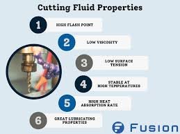
A cutting fluid should have the following properties :

1. High heat absorption for readily absorbing heat developed.

2. Good lubricating qualities to produce low-coefficient of friction.

3. High flash point so as to eliminate the hazard of fire.

4. Stability so as not to oxide in the air.

5. Neutral so as not to react chemically.

6. Odorless so as not to produce any bad smell even when heated.

7. Harmless to the skin of the operators.

8. Harmless to the bearings.

9. Non-corrosive to the work or the machine.

10. Transparency so that the cutting action of the tool may be observed.

11. Low viscosity to permit free flow of the liquid.

12. Low priced to minimize production cost.

Choice of Cutting Fluids

The choice of cutting fluid depends upon the following factors.

1. Type of operation.

2. The rate of metal removal.

3. Material of the workpiece.

4. Material of the tool.

5. Surface finish requirement.

6. Cost of cutting fluid.

Cutting Fluids Types

The types of cutting fluids to be used depends upon the work material and the characteristic of the machining process. For some machining processes, a cutting fluid which is predominantly a lubricant is desirable.

With other machining processes, a cutting fluid which is predominantly a coolant should be used. Cutting fluids are classified in seven main groups. These include water, soluble oils, straight oils, mixed oils, chemical additive oils (sulphurated and chlorinated), chemical compounds and solid lubricants.

1. Water

Water, either plain or containing an alkali, salt or water soluble additive but little or no oil or soap are sometimes used only as a coolant. But water alone is, in most cases, objectionable for its corrosiveness.

2. Soluble Oils

Soluble oils are emulsions composed of around 80 per cent or more water , soap and mineral oil. The soap acts as an emulsifying agent which break the oil into minute particles to dispose them throughout water. The water increases the cooling effect, and the oil provides the best lubricating properties and ensures freedom from rust. By mixing various proportions of water with soluble oils and soaps, cutting fluids with a wide range of cooling and lubricating properties can be obtained.

3. Straight Oils

The straight oils may be (a) straight mineral (petroleum) oils, kerosene, low-viscosity petroleum fractions, such as mineral seal, or higher-viscosity mineral oils, (b) straight fixed or fatty oils consisting animal, vegetable, or synthetic equivalent, lard oil, etc. They have both cooling and lubricating properties and are used in light machining operations.

4. Mixed Oils

This is a combination of straight mineral and straight fatty oil. This blend makes an excellent lubricant and coolant for automatic-screw-machine work and other light machining operations where accuracy and good finish are of prime importance.

5. Chemical-additive Oil

Straight oil or mixed oil when mixed up with sulphur or chlorine is known as chemical additive oil. Sulphur and chlorine are used to increase both the lubricating and cooling qualities of the various oils with which they are combined. Sulfurized mineral oils are commonly used for machining the tough, stringy, low-carbon steels. Chlorinated mineral oils are particularly effective in promoting anti-weld characteristics.

6. Chemical Compounds

These compounds consist mainly of a rust inhibitor, such as sodium nitrate, mixed with a high percentage of water. Chemical compounds have grown in favour as coolants, particularly in grinding and on machined surfaces where formation of rust to be avoided.

7. Solid Lubricants

Stick waxes and bar soaps are sometimes used as a convenient means of applying lubrication to the cutting tool.

Theory of Cutting Fluid

Theory of Cutting Fluid : The basic function of an effective cutting fluid is to reduce kinetic coefficient of friction, Dr. Merchant, one of the pioneers in the theory of metal cutting, has suggested a theory to explain the penetration of cutting fluid.

It is assumed that minute capillaries exist at the tool-chip interface as shown in Fig below on a submicroscopic scale . As the chip move up the tool face, it contacts mainly the tops of the asperities in the point contact zone creating capillaries between the chip and the tool .

These capillaries draw in the cutting fluid which chemically reacts to produce a solid low-shear strength film. Under the condition of high pressure and temperature at the “nascent” chip surface the highly reactive chemical action produces relatively weak solid providing a “sandwich filling” to keep the chip and tool apart thereby reducing friction.

It is well established that small change in tool temperature can produce considerable change in tool life. Cutting fluids directly control the amount of heat at the chip tool face and thereby increase tool life.

Cutting Fluids as Coolant

Cutting fluids are very important in machining processes. They are used to reduce the effects of friction. They are also used to carry away heat in machining operations. Excessive heat can damage the microstructure of metals.

Proper use of coolants can make higher metal removal rates possible. Coolants can also help improve part quality and dimensional accuracy. To increase tool life, better surface finish and increase machining speed, the cutting fluids must be needed for cooling the surface for machining. There are four ways of cooling using the cutting fluids. The cooling systems are as follows:

  1. Flood cooling
  2. Chilled fluid cooling
  3. Mist (spray) cooling
  4. Jet cooling

Flood application delivers fluid to the surface of cutting tool /workpiece by means of a nozzle. Cutting fluids may also be atomized and blown onto the tool /workpiece interface via mist application.

The flood method is the most common method for applying cutting fluids in turning, drilling, and milling process The Flow rates can be such so as to wash away the chips from the cutting region in deep- hole drilling and end milling by using fluid pressures above 1000 kPa.

In this article we learnt what are cutting fluids, its types, properties and theory of cutting fluid. Hope you liked the article. Please share it with your friends and give feedback in the comment section.

Check Out Other Important Topics

Plant Layout – Types, Objectives, Principles, Advantages

Types of Punches – Uses, Working, Applications, Pictures

Types of Dies – Classification, Uses, Pictures

Types of Rivets – Working & Their Uses [with Images]

Types of Fasteners – Uses & Examples [with Pictures]

Foundry Tools And Equipment – List, Names & Images

IC EngineImportant PDFsBoilersSynergy Maritime ExamNaval ArchMEO Class 4
Interview QuestionsDifference BetweenTypes of PumpsAuxiliary MachinesTypes of ValvesHome

why ac is preferred over dc

This article outlines important reasons why AC are preferred over DC. Here’s a refined version of the points you have already made, improving flow and clarity while maintaining simplicity:

Why AC Is Preferred Over DC ?

Here’s a simplified version of your explanation that could work well for a general audience:


Why AC is Preferred Over DC:

  1. Less Power Loss: AC loses less power during transmission from the plant to the grid compared to DC.
  2. Easy Conversion: AC can be easily converted to DC using rectifiers, but converting DC to AC is much harder.
  3. Flexible Voltage Control: With transformers, AC can be “stepped up” or “stepped down” to different voltages, which isn’t possible with DC.
  4. Cost-Effective: Generating AC is cheaper than generating DC power.
  5. AC for Motors: Induction motors, which are common in many appliances, only work on AC power.

AC is Preferred Over DC in a table format:

FactorAC (Alternating Current)DC (Direct Current)
Power Loss During TransmissionLess power loss over long distancesHigher power loss during transmission
ConversionEasily converted to DC using rectifiersHard to convert to AC
Voltage AdjustmentCan be stepped up or down using transformersCannot be stepped up or down easily
Cost of GenerationCheaper to generateMore expensive to generate
Compatibility with MotorsInduction motors work only on ACNot suitable for most induction motors

This table breaks down the key differences between AC and DC clearly and concisely.


Why AC System is Preferred over DC System in Ships

In ships, the AC system is generally favoured over the DC system for several key reasons:

  1. Smaller and Lighter Machines
    AC machines are smaller and more compact for a given power output (kilowatts) compared to DC machines. This is crucial for ships where space is limited, and reducing weight is always a priority.
  2. Ease of Manufacturing High Power Generators
    High-power and high-voltage AC generators can be manufactured more easily, making them ideal for marine applications that require significant power generation.
  3. Voltage Control Using Transformers
    In AC systems, voltage can be easily raised or lowered using transformers. This makes it more efficient for transmission and distribution on the ship, as transformers ensure optimal voltage levels for different operations.
  4. Ease of Maintenance and Voltage Changes
    The AC system is easier to maintain and allows for smoother voltage adjustments using AC transformers, making it more practical for long-term shipboard operations.
  5. Simple AC to DC Conversion
    AC can be easily converted to DC when needed, making the system flexible to use for specific equipment or applications that may require DC power.
  6. Lower Plant Costs
    The plant cost for AC transmission, including components like circuit breakers and transformers, is lower than the equivalent DC transmission setup. This reduces the overall cost of the electrical system on a ship.
  7. Natural Current Interruption
    In an AC system, current periodically drops to zero due to the sinusoidal nature of the waveform. This makes it easier to interrupt the current in case of faults, improving safety and fault detection.
  8. Higher Power-to-Weight Ratio
    AC systems provide a higher power-to-weight ratio, which is especially important in marine environments where weight must be minimized to improve performance and fuel efficiency.
  9. Alignment with Shore Power Practice
    The electrical distribution scheme on ships generally mirrors shore-based practices, which predominantly use AC systems. This alignment makes it easier to connect with shore power when docked, simplifying overall operations.


Demerits of AC System in Ships

While the AC system is preferred for many reasons, it does have some drawbacks:

  1. Faults Can Lead to Major Hazards
    Electrical faults in an AC system can escalate into serious hazards, such as fire or even explosions. This requires strict monitoring and proper safety systems in place to mitigate risks.
  2. Safety Concerns
    Safety is of utmost importance when working with AC systems, especially because of the higher voltages involved. Proper protective gear, such as insulated gloves and clothing, must be worn when handling AC circuits to prevent electrical shocks and injuries.
  3. Higher Losses
    AC systems tend to have more losses due to resistance in conductors and the generation of reactive power. These losses can reduce overall efficiency and increase energy consumption compared to DC systems.

What is Rudder Drop or Rudder wear down and how to measure it ?

What is Rudder Drop ?

Rudder Drop refers to the wear or downward shift of the rudder carrier’s bearing on a ship. As the bearing wears down, the rudder may lower, which can be measured to track the wear over time.

Rudder Drop

Must Read : Propeller Drop

How is Rudder Drop Measured?

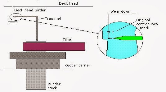
Rudder drop is typically measured using a Trammel Gauge, which is an L-shaped instrument. The process involves:

  1. Marking Reference Points: A point is marked on the rudder stock, and another point is marked on the hull, usually within the steering gear room (on the Deck head girder).
  2. Initial Measurement: The distance between these two points is measured and recorded during the ship’s construction.
  3. Subsequent Measurements: Over time, the same distance is measured. The difference between the original measurement and the current measurement indicates the rudder drop or the extent of bearing wear.

Rudder Clearance and Jumping Clearance

Rudder clearance refers to the space between the rudder and hull. Pads are welded to both components, and this clearance allows for movement and wear. Over time, as the carrier wears down, this clearance, also known as jumping clearance, will increase.

Why is Jumping Clearance Necessary?

Jumping clearance is essential to prevent damage to the steering gear. The clearance ensures that excessive wear does not impact the functionality of the steering system. If this clearance increases significantly, it may indicate excessive wear on the rudder carrier bearing.

Steering Clearance

Steering clearance is the gap between the steering gear and the rudder assembly. Monitoring this clearance is crucial because as the carrier wears down, this gap will shrink, and any significant reduction could affect the overall steering performance of the ship.

In summary, rudder drop, jumping clearance, and steering clearance are all important factors to monitor to ensure the proper functioning and safety of the ship’s steering system.

How a Trammel Gauge Works:

A trammel gauge is a simple yet effective instrument used to measure the distance between two fixed points, typically on large structures like a ship’s rudder system. Here’s a breakdown of how it works:

  1. Structure of the Gauge:
    The trammel gauge is L-shaped, allowing for easy alignment with the two reference points. It has two adjustable pointers or arms that can be positioned to mark the distance between the points being measured.
  2. Reference Points:
  • One point is marked on the rudder stock (the vertical shaft connected to the rudder).
  • The other point is marked on the hull, typically in the steering gear room, on the Deck head girder.
  1. Initial Measurement:
    When the ship is constructed, the distance between these two points is measured and recorded using the trammel gauge. This serves as the baseline measurement for the rudder system.
  2. Subsequent Measurements:
    As the ship is used, wear and tear in the rudder bearing can cause the rudder to “drop” slightly. At regular intervals, the trammel gauge is used again to measure the distance between the same two points.
  3. Rudder Drop Calculation:
    The difference between the original distance (measured during construction) and the current distance (measured during inspection) is called the rudder drop or rudder wear down. This indicates how much the rudder bearing has worn down over time.

By comparing the two measurements, engineers can assess the wear on the rudder’s bearing and determine if maintenance or repairs are needed.

Turbocharger washing Procedure

Turbocharger Washing Procedure: You will Learn the Procedure of Cleaning Turbocharger in Details.

Turbocharger washing Procedure
Fig: Turbocharger washing procedure

Turbocharger is an important components of engine which increase the power to weight ratio of the engine. A turbocharger is an instrument fitted on the engine to increase the overall efficiency of the engine. Turbocharger affects the efficiency of the efficiency of engine. So, we need to washing it properly on time.

Suggested Read : Boiler Gauge Glass Blow through Procedure

What Is Turbocharger Washing

Turbocharger washing is the process of cleaning a Turbocharger for removing solid carbon deposits to keep it in good conditions. It is Important to wash turbocharger time to time between major repairs and ensure the engine runs smoothly. Regular cleaning is important because it helps remove deposits like carbon buildup, which can cause problems like poor engine performance and higher fuel consumption.

Why Washing Of Turbocharger Required ?

Let us first understand why turbocharger washing is necessary. If washing of blade of turbine and blower side is not done then a layer of air and exhaust gas formed on the blade. All Energy of exhaust gas not transfer to blade so, it does not rotate with adequate speed so, air required for combustion is not adequate so proper combustion does not takes place. Thus, we understand how fouling affects efficiency.

As due to fouling of blade there is decrease in efficiency of engine. so, need to do washing procedure of turbocharger on time. According to instructions mentions in the manual of turbocharger , washing is done.

What Important point before turbocharger washing

  • Keep in mind that , if you have not done the washing procedure of blade of blower and turbine from a long time then do not do washing procedure. Before doing washing procedure, make sure a complete overhaul of turbocharger is done. If you have not done overhauling ( if not cleaned for a long time ) and do washing of blade then deposits on the blade will not remove properly. some of the deposits left on blade. When Turbocharger run it create a Noise and heavy vibrations due to imbalancing of blade. It is very difficult to handle and cause break the some important part of the turbocharger.
  • For washing the blade of blower side, a separate connections is provided.
  • Fouling on the blade of exhaust side is less as compare to blower side. It is logical questions, everyone know. It is because due a high temperature and pressure gas falls on the blades and did the work of removing all the deposits accumulated on blade. As exhaust from combustion chamber contain some amount of impurity like caco3, carbon deposits and ash etc. So, some amount of exhaust deposits remain on turbine blade.
  • Sometimes, surveyor ask that , how will you know the efficiency of turbocharger is good. Again, this is tricky questions. Efficiency of Turbocharger can be get from Difference of inlet and outlet temperature of t/c. Because from difference, We can conclude that how much exhaust gas energy is is used or transferred to the blade for rotation.

Turbocharger Washing Procedure for Turbine side of Blade

Note :- When we will do water washing then we reduce the engine rpm. We also use Warm water instead of cold water At the pressure of 4.5 bar. WE do this because cold water and hot surface of blade cause cracking of blade of t/c due to quenching effect.

Procedure :-

  • First inform the bridge that we are going to t/c water washing.
  • Take the wind directions. Why we check wind directions ? it is because of fire hazards.
  • We have to decrease the RPM of engine before doing washing procedure. But speed will not decrease suddenly. Take at least 30 minutes to decrease the speed gradually. Keep decreasing speed till temperature of exhaust gas at the inlet of T/c is approximately 200-230 Degree Celsius.
  • When we reached at required rpm then wait and run the engine the engine at same speed for approximately 10-minutes so that temperature stabilizes.
  • Now open the drain of Turbocharger.

There Are two Valves provided, one for drain and other for supplying warm water.

  • As we already open the drain, now open the valve of water washing. Let it open for 10 minutes. Ninety percent of water get evaporated and ten % of water come from the drain.
  • Water coming out from the drain should be checked and if it is clean that means cleaning procedure is done properly. Now close the drain valve of T/c.
  • Now close the water supply valve. Run the engine at same speed for ten minutes. Then increase speed gradually. Meanwhile check abnormal vibrations or noise from t/c.

This is Water Washing Procedure of Turbocharger on turbine side.

Dry washing of Turbine side

There is a Box provided for putting a grit. Gauge glass fitted on it to check the level of grit.

There are three valve fitted to grit cylindrical box. One valve is for putting grit. another valve for supplying air. One valve is fitted at bottom of box which supply grit or air to turbine. name valve 4, 5 AND 6 in the above figure.

Valve 6 :- For supplying Grit to box.

Valve 5 :- For supplying air.

Valve 4 :- For supplying air of grit to inlet to turbine.

Dry washing is done at high RPM.

Increase the RPM of engine same as mention above to decrease And come speed at required RPM and let it run for 10 minutes and wait for all parameters to come stable. Check the air bottle pressure and drain it.

  1. First inform the bridge and check the directions of wind.
  2. Open the valve 6 and fill the grit in the box. Fill the grit up to 3/4 th level and close the valve.
  3. Open the Valve 4 grit will enter to turbine side.
  4. Open the Valve 5 and provide compressed and wait for a minutes and after that close it.
  5. From the sight glass and help of torch check all grit in turbine side is gone or not. But keep in mind that close the Valve 5 before seeing the conditions of grit,.

This is dry washing procedure of turbine side of turbocharger.

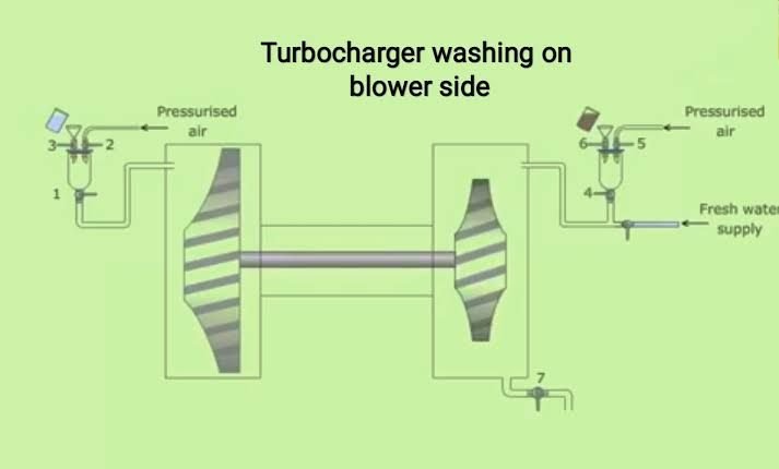
Dry washing of blower side of turbocharger

You to do the dry washing at high RPM. Follow the above procedure to increase the RPM and Run for ten minutes to stabilize all parameters.

Check the air bottle pressure and drain it.

Valve 3 :- For putting grit

Valve 2 :- Supplying air

Valve 1 :- For supplying air to blower side of turbocharger.

Open the Valve 3 and put the grit up to 3/4th level of box. Open the valve 1

Open the valve 2 and provide compressed air. Wait for a minutes and close valve 2 and the Valve 3.

This is all about washing procedure of turbocharger.

Advantages of water washing

The main advantages of water washing is that cleaning of blade is proper and increase the efficiency of T/C.

Disadvantages of water washing

  1. There is more chance on increase of corrosion of blade.. It is due to sulfuric acid in exhaust gas.
  2. If with water washing is not done properly cause noise or imbalance of blade and leads to break.
  3. It takes more time in cleaning.

So, because of the above reason we do grit washing. Note :- During grit washing make ensure that drain of t/c closed.

Difference Between Crosshead and Trunk Type Engine

Difference Between Crosshead and Trunk Type Engines

Crosshead and trunk type engines are two types of piston engines, each with distinct designs and applications. Here’s a detailed comparison:

Crosshead Engine

  • Design: It uses a piston rod and a crosshead assembly to separate the piston from the crankshaft. This design prevents lateral forces from acting on the piston, improving the durability of the engine.
  • Lubrication: Crosshead engines have separate lubrication systems for the cylinder and the crankcase, ensuring that high-pressure, high-temperature areas receive adequate lubrication.
  • Torque and Speed: These engines operate at low speeds and are ideal for large, low-speed applications like marine propulsion due to their high torque generation.
  • Size: Crosshead engines are taller and more complex because of their additional components, including the crosshead mechanism.
  • Maintenance: The separate lubrication system means less contamination in the crankcase oil, reducing maintenance costs and increasing engine life.

Trunk Type Engine

  • Design: The piston is directly connected to the crankshaft via a connecting rod without a crosshead assembly. This simplifies the engine but subjects the piston to side forces, which can lead to more wear.
  • Lubrication: A single lubrication system serves both the cylinder and the crankcase, which simplifies the design but can lead to more contamination.
  • Torque and Speed: Trunk engines are better suited for medium to high-speed operations, offering high power in compact designs, making them ideal for smaller vessels or auxiliary power units.
  • Size: These engines are more compact and shorter, requiring less vertical space.
  • Maintenance: The combined lubrication system increases the risk of contamination, resulting in higher wear and more frequent maintenance.

Difference Between Crosshead and Trunk Type Engines

Below is a detailed comparison between the two:

FeatureCrosshead EngineTrunk Type Engine
DesignUses a crosshead assembly to separate the piston from the crankshaft, reducing side thrust.The piston is directly connected to the crankshaft via a connecting rod, causing lateral forces on the cylinder.
LubricationSeparate systems for cylinder and crankcase lubrication.Single lubrication system for both the cylinder and crankcase.
Speed and PowerLow-speed, high-torque engines, ideal for large applications like marine propulsion.Medium to high-speed engines, suitable for smaller vessels and auxiliary units.
SizeLarger and taller due to the crosshead mechanism.More compact, requiring less vertical space.
MaintenanceEasier maintenance due to separate lubrication systems, leading to less contamination.Higher wear and contamination due to a combined lubrication system.
ApplicationsHeavy-duty applications such as large ships and low-speed operations.Used in smaller marine vessels, auxiliary engines, and high-speed machinery.
Cost and ComplexityMore expensive and complex to manufacture.Less expensive, simpler design.