What is cyclone separator
A cyclone separator, often referred to simply as a cyclone, is a device used to separate particles from a gas or liquid stream based on their size and density differences. It operates on the principle of centrifugal force, which causes the heavier particles to move outward toward the walls of the cyclone while the lighter particles and gas move toward the center and eventually exit through an outlet.
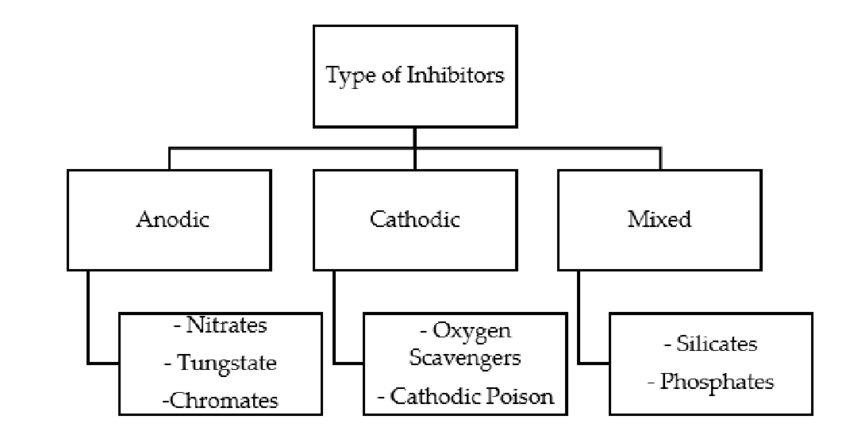
Must Read : Corrosion Inhibitor
cyclone separator construction
A cyclone separator consists of several key components that work together to achieve the separation of particles from a gas or liquid stream. Here’s an overview of the construction and main components of a cyclone separator:
- Cyclone Body: The main body of the cyclone separator is typically cylindrical or conical in shape and is responsible for containing the swirling gas or liquid mixture. It provides the space where the separation process takes place.
- Inlet: The inlet is the point where the gas or liquid mixture enters the cyclone separator. It is often designed to introduce the mixture tangentially into the cyclone chamber, which initiates the swirling motion.
- Vortex Finder: The vortex finder is a cylindrical tube located at the center of the cyclone chamber and extending vertically from the top to the bottom. It guides the upward-flowing clean gas or liquid stream out of the separator.
- Cone: The cone is the conical-shaped lower part of the cyclone chamber. It plays a crucial role in directing the downward flow of separated particles or droplets towards the collection area.
- Collection Area: At the bottom of the cyclone separator, there is a collection area where the separated particles or droplets accumulate. This can be a hopper, a collection bin, or a similar structure.
- Outlet: At the top of the cyclone chamber, there is an outlet for the clean gas or liquid to exit the separator. The outlet can be connected to a duct or pipeline for further processing or discharge.
- Gas-Liquid Separator (Optional): In some applications, especially where a mixture of gas and liquid is being separated, a gas-liquid separator may be incorporated. This component helps to separate the liquid phase from the gas phase before they exit the separator.
- Support Structure: The cyclone separator is often mounted on a support structure or frame that holds it in place and provides stability. This structure might also include provisions for maintenance access and observation.
- Pressure Gauge and Instruments (Optional): Some cyclone separators might include pressure gauges or instruments to monitor the pressure drop across the separator, which can provide insights into the separator’s performance.
- Material and Coating: Cyclone separators are typically constructed from materials that can withstand the conditions of the process fluid, including factors like temperature and chemical compatibility. In some cases, internal surfaces may be coated to prevent wear due to abrasive particles.
- Outlet Valves (Optional): Depending on the design and application, outlets for removing collected particles or droplets might include valves or other mechanisms for controlled discharge.
The construction of cyclone separators can vary based on factors such as the application, operating conditions, and the specific requirements of the process. While the core components remain consistent, variations in size, shape, material, and additional features can cater to a wide range of industrial needs.
Cyclone Separator Working Principle
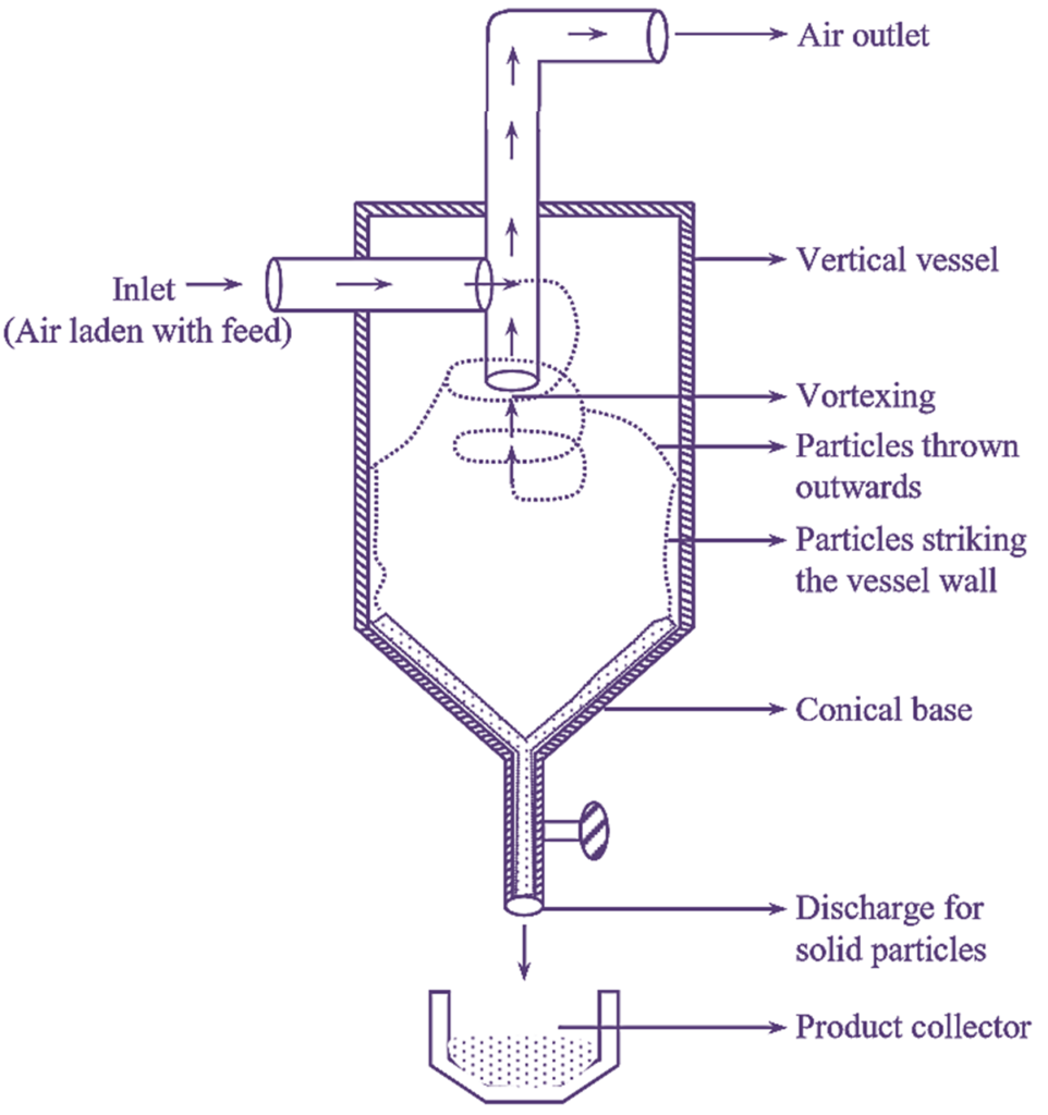
A cyclone functions as a centrifugal separator, driven by the mass of particles that are compelled to migrate towards the outer boundaries due to centrifugal force. As incoming air enters, it inherently adopts a rapid and circular motion, creating what’s referred to as a “double vortex.” This dual spiral movement encompasses an external stream, which follows a descending spiral path, and an internal stream, which ascends spirally. At the junction where these streams interact, air transitions between them. This dynamic pushes airborne particles towards the periphery, causing them to exit the separator through a collection mechanism positioned at the bottom.
Typically, the air velocity within a cyclone ranges from 10 to 20 m/s, with approximately 16 m/s being the most prevalent. Should the velocity fluctuate, especially with lower speeds, the efficiency of particle separation experiences a significant decline.
Cyclone Separator Working
The operation of a cyclone separator is based on the principles of centrifugal force and the creation of a swirling airflow pattern. Here’s a step-by-step explanation of how a cyclone separator works:
- Inlet: The mixture of gas or liquid containing particles or droplets enters the cyclone separator through an inlet located at the top.
- Tangential Entry: The mixture is introduced tangentially into the cyclone’s cylindrical or conical chamber. This entry imparts a swirling motion to the incoming flow, setting up a cyclonic vortex.
- Centrifugal Force: As the mixture spirals downward due to the swirling motion, centrifugal force is generated. This force pushes the heavier particles or droplets towards the outer walls of the chamber. Lighter particles are carried towards the center by the faster-moving air.
- Double Vortex Formation: Within the chamber, two distinct streams are established: an outer downward-flowing stream and an inner upward-flowing stream. This is known as the “double vortex.” The outer stream carries particles towards the walls, while the inner stream carries cleaner air towards the center.
- Interchange Zone: At the interface between the two vortex streams, there is an area where air from the inner vortex exchanges with air from the outer vortex. This exchange region plays a crucial role in particle separation.
- Particle Separation: The heavier particles or droplets in the mixture experience stronger centrifugal forces and are pushed towards the outer edges of the chamber. As they move outward, they gradually lose their momentum and settle towards the bottom of the chamber.
- Clean Air or Liquid Outlet: In contrast, the inner vortex carries cleaner air or liquid upwards towards the center of the chamber. At the top of the cyclone chamber, there is an outlet for the clean air or liquid to exit the separator.
- Particle Collection: The separated particles or droplets continue to move downward and accumulate at the bottom of the cyclone chamber, forming a cone-shaped pile. This collected material can be periodically removed through a discharge mechanism.
- Efficiency and Speed: The cyclone’s efficiency depends on factors like the design, dimensions, and the velocity of the incoming flow. An optimal operating speed ensures effective separation; deviations from this speed can affect the separator’s performance.
In summary, a cyclone separator uses the principles of centrifugal force and swirling motion to separate particles or droplets from a gas or liquid stream. The combination of these forces causes particles to move outward and downward along the chamber’s walls, while cleaner gas or liquid moves upward in the center. The double vortex and interchange zone enhance the efficiency of particle separation, making cyclone separators effective tools for various industrial applications.
cyclone separator design
Designing a cyclone separator involves considering various factors to ensure efficient particle separation and optimal performance. Here are key aspects to consider during the design process:
- Particle Characteristics: Understand the size, density, and shape of the particles or droplets you intend to separate. This information helps determine the cyclone’s dimensions and inlet design.
- Inlet Design: The inlet should introduce the mixture tangentially into the cyclone chamber to establish the swirling motion. The angle of entry and the design of the inlet tube affect the cyclone’s efficiency.
- Cyclone Dimensions: The diameter and height of the cyclone chamber impact separation efficiency. A larger diameter can accommodate larger particles, while a taller cyclone provides more space for particle settling.
- Vortex Finder Length: The length of the vortex finder tube affects the amount of clean gas or liquid that exits the separator. It should be chosen to match the desired separation efficiency.
- Cone Angle: The angle of the cone at the bottom of the cyclone chamber influences the downward flow of separated particles. A steeper cone angle can enhance particle collection.
- Gas-Liquid Separation (if needed): If separating a mixture of gas and liquid, consider incorporating a gas-liquid separator to prevent liquid carryover.
- Pressure Drop: Consider the pressure drop across the cyclone, which affects the energy required to drive the flow and can impact the overall process.
- Material Selection: Choose materials that can withstand the fluid’s temperature, corrosiveness, and abrasiveness. Consider coatings to prevent wear and corrosion on internal surfaces.
- Particle Discharge: Determine how the separated particles or droplets will be collected and discharged from the bottom of the cyclone. Design a suitable collection mechanism.
- Operating Conditions: Consider factors such as temperature, pressure, flow rate, and fluid properties. These factors influence cyclone efficiency and material selection.
- Efficiency vs. Pressure Drop: There’s often a trade-off between separation efficiency and pressure drop. Increasing efficiency might lead to higher pressure drops, affecting system performance.
- Modeling and Simulation: Utilize computational fluid dynamics (CFD) software to simulate airflow patterns, particle trajectories, and pressure distribution within the cyclone. This helps optimize design parameters.
- Testing and Validation: Prototype testing helps verify the cyclone’s performance under real-world conditions. Adjustments may be needed based on testing results.
- Maintenance Considerations: Design the cyclone with access points for inspection, cleaning, and maintenance. Ease of maintenance reduces downtime.
- Scale-Up Considerations: If designing for an industrial application, ensure that the design is scalable and can handle larger flows and particles.
- Regulatory Compliance: Consider any relevant industry standards and regulations related to safety, emissions, and environmental impact.
Successful cyclone separator design requires a balance between these factors to achieve the desired separation efficiency while meeting the specific needs of the application. It’s often beneficial to collaborate with engineers experienced in fluid dynamics and separation processes during the design process.
Application of Cyclone Separator
Cyclone separators find a wide range of applications across various industries due to their ability to effectively separate solid particles or liquid droplets from gas or liquid streams. Some common applications of cyclone separators include:
- Air Pollution Control: Cyclone separators are used in industries like cement, power generation, and metallurgy to remove particulate matter from exhaust gases before they are released into the atmosphere. This helps in complying with environmental regulations and reducing air pollution.
- Dust Collection: In woodworking shops, grain processing facilities, and other industries where dust is generated, cyclone separators are used to collect and remove airborne dust particles, preventing them from contaminating the workspace or being released into the air.
- Chemical Processing: Cyclone separators are employed in chemical processing plants to separate solid catalyst particles from reaction products or to remove impurities from chemical processes.
- Oil and Gas Industry: Cyclone separators are used in the oil and gas industry to separate sand, particles, and other impurities from wellhead fluids before further processing. They are also used in natural gas pipelines to remove liquid droplets and solid particles from the gas stream.
- Food and Beverage Industry: Cyclone separators can be used to remove foreign particles from food and beverage products, ensuring the final product’s quality and safety.
- Agriculture: In grain handling facilities, cyclone separators are used to separate foreign materials, dust, and debris from harvested grains and seeds.
- Mining and Mineral Processing: Cyclone separators are utilized in mining operations to separate particulate matter from slurries and liquids, aiding in the separation of valuable minerals from waste material.
- Wood Processing: In sawmills and wood processing plants, cyclone separators are used to separate wood chips, sawdust, and other debris from the air and material streams.
- Plastics and Polymer Industry: Cyclone separators help in separating plastic pellets, dust, and contaminants from the production process, ensuring the quality of the final plastic products.
- Wastewater Treatment: Cyclone separators can be used in wastewater treatment facilities to separate solid particles and sediments from wastewater before further treatment or disposal.
- Pneumatic Conveying Systems: Cyclone separators are often used in pneumatic conveying systems to separate solid particles from the conveying air, preventing blockages and maintaining system efficiency.
- Biogas Production: In biogas production plants, cyclone separators can help remove moisture, solid particles, and impurities from biogas before it is used for energy production.
These are just a few examples of the many applications of cyclone separators across various industries. The versatility and relatively simple design of cyclone separators make them a popular choice for particle separation and removal tasks in industrial processes.
Advantages of cyclone separator
Cyclone separators offer several advantages in various industrial applications due to their simple design and effective particle separation capabilities. Some of the key advantages of cyclone separators include:
- Effective Particle Separation: Cyclone separators are highly effective at separating solid particles or liquid droplets from gas or liquid streams, particularly for larger particles. Their ability to achieve efficient separation is attributed to the centrifugal force generated by the swirling motion within the separator.
- Low Operating Costs: Cyclone separators have relatively low operating and maintenance costs. They don’t require consumable filter media, and their simple design reduces the need for frequent maintenance or replacement of parts.
- Minimal Maintenance: Due to their uncomplicated design, cyclone separators have fewer moving parts, resulting in reduced wear and tear. This leads to decreased maintenance requirements and downtime, making them suitable for continuous industrial processes.
- Compact Size: Cyclone separators are compact in size compared to some other particle separation technologies. This makes them suitable for installations where space is limited.
- Robust Construction: Cyclone separators are often constructed from durable materials such as stainless steel or abrasion-resistant alloys. This enables them to withstand harsh operating conditions, high temperatures, and corrosive environments.
- High-Temperature Applications: Cyclone separators can be designed to handle high-temperature gas streams, making them suitable for applications involving hot gases or industrial processes that produce elevated temperatures.
- Scalability: Cyclone separators can be easily scaled up or down based on the specific requirements of an application. This scalability makes them adaptable to different flow rates and particle loads.
- Energy Efficiency: Cyclone separators don’t require significant energy input to operate, as their separation is primarily driven by the centrifugal force created by the swirling motion. This can contribute to energy savings in industrial processes.
- No Moving Parts in the Flow Path: The design of cyclone separators ensures that there are no moving parts in the main flow path of the gas or liquid stream. This minimizes the risk of clogging or breakdowns due to particles becoming trapped in moving components.
- Reliable Performance: Cyclone separators provide consistent and reliable performance over time. They are less susceptible to variations in operating conditions and can maintain their separation efficiency across a wide range of flow rates.
- Adaptability: Cyclone separators can be combined with other equipment, such as filters or scrubbers, to achieve finer particle separation or to handle specific types of particles or contaminants.
- Environmentally Friendly: Cyclone separators can contribute to environmental protection by effectively removing particles or droplets from exhaust gases, reducing air and water pollution.
While cyclone separators have many advantages, it’s important to note that their efficiency may decrease for smaller particles. In such cases, additional equipment or multi-stage separation systems might be necessary to achieve the desired level of particle removal.
Disadvantages of cyclone separator
While cyclone separators offer several advantages, they also come with certain limitations and disadvantages that should be considered when selecting them for a particular application. Some of the disadvantages of cyclone separators include:
- Limited Particle Size Range: Cyclone separators are more effective at removing larger particles and droplets. Their efficiency decreases as particle size decreases, which means they might not be suitable for applications requiring very fine particle separation.
- Particle Re-entrainment: In some cases, smaller particles separated by the cyclone might be re-entrained back into the gas or liquid stream, reducing overall separation efficiency. This is more likely to occur with lighter particles and in situations where the cyclone is not operating optimally.
- Pressure Drop: Cyclone separators can create a pressure drop within the system due to the cyclonic motion and the redirection of the gas or liquid flow. This pressure drop can affect the overall efficiency of the process and might require additional energy to overcome.
- Inefficient for Low Concentrations: Cyclone separators are more effective when dealing with higher concentrations of particles. In applications with low particle concentrations, their efficiency might be insufficient.
- Complexity in Multistage Systems: For applications requiring very high particle separation efficiency, a single cyclone might not suffice. In such cases, a multistage cyclone system or combination with other separation methods might be needed, increasing complexity.
- Sensitive to Flow Variations: Cyclone separators’ performance can be affected by changes in flow rate, particle size distribution, and other process variables. Variations in these parameters can impact their efficiency.
- Space Requirements: Although cyclone separators are relatively compact, systems that require multiple cyclones or additional equipment for optimal performance can take up more space.
- Particle Buildup and Wear: Over time, the walls of the cyclone chamber can experience particle buildup, which might require periodic cleaning. Also, abrasive particles can cause wear on the chamber walls, affecting long-term performance.
- Limited Separation of Gases: Cyclone separators are primarily designed for separating solid particles from gas or liquid streams. Separating one gas from another can be more challenging and might require modifications to the basic cyclone design.
- Complex Design for Specialized Applications: While basic cyclone designs are simple, more specialized applications (such as handling high temperatures, corrosive materials, or explosive atmospheres) might require more complex and expensive designs.
- Efficiency Trade-offs: Achieving very high separation efficiency might require optimizing the cyclone design, which can lead to trade-offs with other factors like pressure drop or maintenance requirements.
- Efficiency Reduction with Wear: As the cyclone chamber’s internal surfaces wear over time due to particle impacts, its efficiency can decrease.
When considering the use of cyclone separators, it’s important to assess the specific requirements of the application, including particle size distribution, desired separation efficiency, operating conditions, and space limitations, to determine whether the advantages outweigh the disadvantages in a given context.
Reference : https://en.wikipedia.org/wiki/Cyclonic_separation